Table of Contents
Advertisement
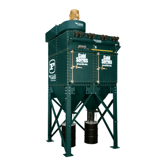
Gold Series
Gold Series
Dust
Dust
Collector
Collector
Installation,
Installation,
Operation and
Operation and
Maintenance
Maintenance
Farr Air Pollution Control
PO Box 9080 / 3501 North Airport Road
Jonesboro, Arkansas 72401
1-800-479-6801
1-800-222-6891 Fax
wwwfarr.com/apc
Customer:
Customer:
Location:
Location:
Job #:
Local Rep:
Rep. Phone #:
Document #C-1000-21 Rev. D
Advertisement
Table of Contents
Troubleshooting

Summary of Contents for Farr Gold Series
- Page 1 Installation, Operation and Operation and Maintenance Maintenance Customer: Customer: Location: Location: Farr Air Pollution Control Job #: PO Box 9080 / 3501 North Airport Road Jonesboro, Arkansas 72401 Local Rep: 1-800-479-6801 Rep. Phone #: 1-800-222-6891 Fax wwwfarr.com/apc Document #C-1000-21 Rev. D...
-
Page 2: Table Of Contents
ILTER ODULE 310.6 D ..........................12 ISCHARGE CCESSORIES 310.7 D ..........................13 LIDE 310.8 P ............................13 LATFORM ADDER SECTION 320-ATTACHING DUCT WORK TO YOUR GOLD SERIES............14 320.1 I .............................15 NLET ESIGN 320.2 I .............................16 NLET LANGES 320.3 R ......................16 EMOTE OUNT ISCHARGES 320.4 T... - Page 3 SECTION 400-OPERATION OF YOUR EQUIPMENT ..................31 400.1 S ............................31 YSTEM PERATION 400.2 F ............................32 ILTER LEANING 400.3 C ......................33 LEANING YSTEM OMPONENTS 400.4 D DCT1000 A .................34 WYER UTOMATIC IMER ONTROLLER 400.5 NCC DT-10 (D .............37 ETERMINATOR UTOMATIC IMER ONTROLLER 400.6 G P-4 A ................41...
- Page 4 GOLD SERIES ACCESSORIES Following is a list of common accessories to Gold Series collectors that are not covered in this manual. If your collector includes any of the accessories, the documentation title and/or number will be listed beside the accessory. The documentation will be included with this manual submittal.
-
Page 5: Introduction
This manual covers the installation, operation and maintenance of the Gold Series Dust Collector. This is a piece of air cleaning equipment that is used to eliminate dust contaminants from the environment making the facility or plant a healthier and safer work place. -
Page 6: Section 100-Safety Precautions
Farr relies on the skills and expertise of its customer and any consulting engineers and/or installing contractors hired by that customer to properly design and install the dust collection system of which Farr equipment is a part. It is the responsibility of the end user of this equipment to take the necessary precautions to minimize the inherent risks associated with combustible dust. -
Page 7: Ock Out Ag Out Equirements
Identifies hazards associated with rotating machinery. Marks the location of an Indicates the hazard of being explosion relief vent. In trapped inside a dust collector. If the event of an explosion the main fan is activated the in the dust collector collector door would be sucked there is a potential for shut. -
Page 8: Section 200-Receiving Your Equipment
The structural integrity of the housing will be adversely affected by large dents. Farr should immediately be notified of any structural damage to your equipment. It is the purchaser’s responsibility to file shortage reports and damage claims with the carrier and your Farr representative. -
Page 9: Ow Your Equipment I S Shipped
200.3 How Your Equipment Is Shipped It is Farr’s goal to ship our products as economically and practically as possible. In order to save our customers shipping costs, it is our goal to load your collector on as few trucks as necessary. The number and size of trucks required to transport your collector will depend solely on the size of your unit. -
Page 10: Section 300-Installation Of Your Equipment
SECTION 300-INSTALLATION OF YOUR EQUIPMENT Table 300.1: Gold Series Assembly Tools The following items may be required to install your equipment depending on configuration and installation requirements: Only trained, authorized personnel should be permitted to service or maintain electrical or safety components. -
Page 11: Section 310-Assembling Your Gold Series
SECTION 310-ASSEMBLING YOUR GOLD (FIELD INSTALL) SERIES FAN MOUNT PANEL 310.1 Hardware FILTER MODULE Refer to Figure 310.1 for typical assembly points of a standard collector. Refer to the General Dimension drawings for specifics, such as item part numbers, inlet and outlet locations, foundation dimensions and accessories. -
Page 12: Ischarge Accessories
5/8" BOLT, FLAT WASHER (2 SIDES), LOCK WASHER & NUT (TYP ALL CONNECTIONS) KNEE BRACE SLOT FOR LIFTING 5/8 NUT CORNER SUPPORT 5/8 LOCK WASHER 5/8 BOLT BRACKET 5/8 FLAT WASHER FIGURE 310.2 (GS 32 SHOWN) mount fan remove the upper side panel from the side you intend to make your fan duct flanged connection. -
Page 13: Rum Kit /Slide Gate
310.7 Drum Kit/Slide Gate LIFTING LUG Clean and apply rope caulk to the top FULL MODULE surface of the slide gate flange. Bolt (4 CARTRIDGES) the slide gate to the hopper discharge flange; making sure that HALF MODULE the slide gate is oriented so that (2 CARTRIDGES) there is no interference when the handle is pulled out. -
Page 14: Section 320-Attaching Duct Work To Your Gold Series
SECTION 320-ATTACHING DUCT WORK TO YOUR GOLD SERIES This section covers flange details and design guidelines for ducting to your Gold Series dust collector. The following figures show the different sizes of inlet and outlet flanges. 60" 1-1/8" 24" 1-1/8"... -
Page 15: 320.1 Inlet Duct Design
1" 17" 38" 1" 3/8-16 UNC 3/8-16 UNC 3 @ 4" 3-1/2" = 12" 2" 9 SPA @ 4" =36" 2" 3-1/2" 19" 40" Figure 320.6 Figure 320.7 TOP OUTLET FLANGE TOP OUTLET FLANGE (FULL PANEL) (HALF PANEL) 320.1 Inlet Duct Design When you run ducting to your collector, it is important to follow these guidelines. -
Page 16: Emote Mount Fan Discharges
Figure 320.9 - Top View 320.2 Inlet Flanges Depending on the size and orientation of your Gold Series collector, the inlet will have one or more of three inlet designs. These inlets are configured and classified with the number of modules that the collector uses to support the inlet plenum. -
Page 17: Section 330-Field Utility Connections
SECTION 330-FIELD UTILITY CONNECTIONS COMMON JUMPER (1 PER SOLENOID) SOLENOID TO GROUND DIAPHRAGM VALVE 90 PSI (MIN) COMPRESSED AIR (1" NPT) LOW DP AIR CONSUMPTION TIMER (SEE TABLE 330.3) 120/1/50-60 VAC CONNECT TO MAGNEHELIC GAGE IF YOU DO NOT HAVE AIRLINE CONNECTIONS ON YOUR TIMER HIGH DP 1/4"... -
Page 18: Otor Connections
Farr can supply the fan, motor starter, and rotary air locks (or other discharge devices) for our dust collectors. However, the customer or Farr representative may elect to supply the fan and other accessories. -
Page 19: Imer Control
330.2 Timer Control This discussion refers to standard equipment that uses 120/220 VAC, single phase, 50/60 Hz power. Refer to your General Dimensions drawing to confirm the electrical requirements of your equipment. Connection instructions are the same regardless of the voltage source. Refer to the documentation attached to this manual and the timer control box for further information regarding the installation of your specific control. - Page 20 Table 330.3.1 shows the number of solenoids and automatic timer controller outputs for the standard Gold Series models. For GS2 through GS60 models, there are at least as many timer outputs as there are solenoids. Each timer output connects to an individual solenoid. For GS72 through GS120 models, there are more solenoids than timer outputs.
-
Page 21: Ifferential Pressure (Dp) Connections
Farr recommends that the compressed air supply be kept at a dew point of -85 F. Make provisions for draining any condensate from the air reservoir with an automatic tank drain or by other means. - Page 22 12.8 24.0 30.8 18.0 23.1 14.4 18.5 12.0 15.4 10.3 13.2 11.6 10.3 Table 330.5.1 Gold Series Dust Collector Air Consumption - 1" Diaphragm Valve 200 msec ON TIME 150 msec ON TIME 100 msec ON TIME OFF TIME (sec)
-
Page 23: Prinkler Onnections
Graph 330.5.1 Gold Series Dust Collector Air Consumption - 1-1/2" Diaphragm Valve 200 msec ON TIME 150 msec ON TIME 100 msec ON TIME OFF TIME (sec) Graph 330.5.2 330.6 Sprinkler Connections If your collector is equipped with a sprinkler system, locate the sprinkler connection coupling(s). Refer to the General Dimensions drawing for locations. - Page 24 runs along the bottom of the filter module. All of the sprinkler heads are supplied through a single coupling, welded near the bottom of a lower side panel. SPRINKLER CONNECTION COUPLING SPRINKLER HEAD (SEE SEE TABLE 330.6.1 FOR TABLE 330.6.1 FOR QUANTITY) CONNECTION SIZE AND NO.
-
Page 25: Section 340-Explosion Vents
Following is a list of publications that are highly recommended by Farr for use in determining if the installation of your dust collection system meets all of the NFPA recommendations with regards to conveying, collecting and processing explosive dusts. -
Page 26: Xplosive Dusts
• Appropriate signs should be posted to provide warning as to the location of a vent. Replacement decals are available from Farr and are listed in the spare parts section of this manual. • A vent closure should be inspected and properly maintained in order to ensure dependable operation. In some cases, ensuring dependable operation can necessitate replacing a vent closure. -
Page 27: Ystem Ducting On Combustible Dusts
340.10 Vent Inspection and Maintenance Farr incorporates two styles of explosion vents on their dust collectors. One is a rupture diaphragm and the other is a hinged door. Explosion vents should be inspected every three months. The inspection and maintenance points are outlined below. -
Page 28: Section 350-Filter Installation/Replacement
SECTION 350-FILTER INSTALLATION/REPLACEMENT 1. New units ship with filter cartridges installed. Disconnect electrical power to the fan and control box. Disconnect compressed air service from the compressed air header. Bleed all air from the air header. Perform an OSHA approved lock-out/tag-out procedure on these and any other energy sources (Refer to Section 100.3 of this manual for more information). -
Page 29: Section 360-Precoating Of Filters
Figure 350.3 Figure 350.4 - Clamp Bars Open SECTION 360-PRECOATING OF FILTERS In applications where the dust concentration is high and/or the dust particles are large (more than 0.5 microns), pre-coating of the filters is not required. In applications where the dust concentration is low and/or the dust particles are small (less than 0.5 microns), pre-coating will result in a higher initial efficiency and extended filter life. - Page 30 9. Record the magnehelic gauge reading and set the fan damper to correspond to the system design airflow. Airflow can be measured by means of a Pitot tube, anemometer or similar device. 10. Remove any remaining pre-coat dust from the outlet ducting, SMF housing and discharge container. Discard according to local codes and procedures.
-
Page 31: Section 400-Operation Of Your Equipment
The Gold Series dust collector described in this manual is designed for the collection of welding fumes and/or the capture of airborne particles generated from mixing, sanding, grinding and cutting operations involving wood, metal, fiberglass, plastics, advanced composites or similar materials. -
Page 32: Ilter Cleaning
• Inertial Collection – Dust particles strike the fibers placed perpendicular to the airflow direction instead of changing direction with the air stream. • Interception – Particles that do not cross the fluid streamlines come in contact with fibers because of the fiber size. -
Page 33: Leaning Ystem Omponents
400.3 Cleaning System Components HEADER (COMPRESSED AIR PRESSURE RESERVOIR) A header is provided with a 1 in. NPT coupling at each end. Supply the header with clean, dry compressed air between 90 and 105 psi. The air supply line should be equipped with a manual shut-off valve, a filter/separator, an air regulator and a pressure gauge, all located near the unit. -
Page 34: Wyer Dct1000 Automatic Timer Controller
400.4 Dwyer DCT1000 Automatic Timer Controller The DCT1000 was designed for on-demand or continuous cleaning applications. Continuous cleaning applications do not require external inputs and can be used for time based “on-demand” cleaning through use of the cycle delay feature. For on-demand applications, the plug-in pressure module can be used to take full advantage of all the DCT1000 features. - Page 35 Low Alarm Setup The operation of the Low Alarm Setup is identical to the High and Low Limit Setup. The Low Alarm default is 1.0” w.c. The upper settable value is the calibration pressure of the pressure module and the lower limit is zero.
- Page 36 NEMA 4X ENCLOSURE SELECTOR SWITCH Figure 400.4.1 Dwyer DCT1000 Timer Enclosure...
-
Page 37: 400.5 Ncc Dt-10 (Determinator) Automatic Timer Controller
PLUG-IN PRESSURE MODULE 3 POSITION SELECTOR DWYER INSTRUMENTS ALARM ALARM SWITCH HIGH COM LOW MODE RESET COM MICHIGAN CITY, IN LIMIT LIMIT ALLEN BRADLEY PN-800T-J2-KU7-B 4-20 MA OUTPUT W/NAMEPLATE PROCESS (IN H O) PN-800T-X625 LAST OUTPUT TIME OFF (SEC) TIME ON (MSEC) SETUP STATUS HIGH LIMIT... - Page 38 6.88 6.25 .25 DIA MOUNTING HOLE (4 PLACES) RS232 CONNECTOR OUTPUT STEP ITEM VALUE ALARM DIFFERENTIAL PRESSURE (DP) CANCEL REMOTE ALARM INCHES OF WATER DP CYCLE DOWN INPUT (OPTIONAL) OR BYPASS MODE SELECT (OPTIONAL) camfil ALARM BYPASS INPUT INPUT INTELLIGENT DUST CONTROL DIFFERENTIAL PRESSURE ALARM MODEL NO.: SEE TABLE...
- Page 39 OPERATING MODE DISPLAYS SETUP ON STARTUP AND AFTER RESET DISPLAYS P = X.X WHEN RUNNING Display Keypad ITEM ITEM OUTPUT STEP ITEM VALUE DISPLAY FREEZES AT P = X.X ALARM CANCEL ITEM VALUE ITEM ITEM Use the Item Keys to: 1) Navigate within the OUTPUT = X DISPLAYS LAST OUTPUT TRIGGERED...
- Page 40 TO "A" TO "C" NO CYL = X CYL DN = Y NUMBER OF CYCLES SKIP IF CYL DN = N VALUE CYL DN = N WHEN CYCLE DOWN IS ENABLED USE THE UP AND DOWN VALUE KEYS TO SET ITEM THE NUMBER OF CLEAN DOWN CYCLES UP TO A MAX OF 15.
-
Page 41: Oyen T-4 And P-4 Automatic Timer Controller
400.6 Goyen T-4 and P-4 Automatic Timer Controller The T-4 Automatic Timer Controller uses a solid-state timer control to continuously clean the cartridges with the user inputting the length of pulse and the interval between pulses. The P-4 Automatic Timer Controller uses a differential pressure transmitter connected to a solid-state timer control to initiate the cleaning cycle at user input differential pressure set points. - Page 42 Set the high and low-pressure drop settings using the right and left hand knobs, respectively, on the face of the gauge. The timer will initiate pulsing of the valve solenoids when the collector pressure drop rises to the “high” set point and continue until the collector pressure drop is lowered to the “low” set point. Zero the photohelic gauge using the adjustment screw on the face of the gauge.
- Page 43 Programming Example 1 0 0 STEP 1 – ON TIME – Press the “Select” button until the “ON TIME” LED indicator is illuminated, then press the “Adjust” button until the required ON TIME in milliseconds is ON TIME #OFF'S shown on the Digital Readout (100 milliseconds illustrated). OFF TIME LOCKED #VALVE...
-
Page 44: An Operation
400.7 Fan Operation Consult the information packet attached to your fan before proceeding with installation and wiring. If your fan does not include an information packet contact the fan supplier. If Farr supplied your fan, contact Farr Customer Service at (1-800-479-6801). - Page 45 NYB 146GI-1.5-60-10 1350 CFM, 11.1" H O, 3500 RPM, 5.0 BHP 16.0 14.0 STATIC PRESSURE 12.0 BRAKE HORSEPOWER 10.0 1,100 1,300 1,500 1,700 1,900 2,100 2,300 2,500 FLOW RATE (cfm) Figure 400.7.2 NYB 15PLR-2.0-60-9 2000 CFM, 9.1" H O, 3500 RPM, 4.3 BHP 12.0 STATIC PRESSURE 10.0...
- Page 46 NYB 15PLR-3.0-60-9 3000 CFM, 9.1" H O, 3500 RPM, 6.4 BHP 12.0 STATIC PRESSURE 10.0 BRAKE HORSEPOWER 1,500 2,000 2,500 3,000 3,500 4,000 4,500 5,000 FLOW RATE (cfm) Figure 400.7.4 NYB 18PLR- 4.0-60-9 4000 CFM, 9.1" H O, 3500 RPM, 9.1 BHP 16.0 STATIC PRESSURE 14.0...
- Page 47 NYB 18PLR-6.0-60-9 6000 CFM, 9.1" H O, 3500 RPM, 13.6 BHP 16.0 14.0 STATIC PRESSURE 14.0 13.5 BRAKE HORSEPOWER 12.0 13.0 10.0 12.5 12.0 11.5 11.0 3,000 3,500 4,000 4,500 5,000 5,500 6,000 6,500 7,000 7,500 FLOW RATE (cfm) Figure 400.7.6 NYB 18PLR-8.0-60-9 8000 CFM, 9.1"...
- Page 48 NYB 18PLR-10.0-60-9 10000 CFM, 9.1" H O, 3500 RPM, 22.7 BHP 16.0 23.0 STATIC PRESSURE 22.5 14.0 BRAKE 22.0 HORSEPOWER 12.0 21.5 10.0 21.0 20.5 20.0 19.5 19.0 18.5 18.0 4,000 5,000 6,000 7,000 8,000 9,000 10,000 11,000 12,000 FLOW RATE (cfm) Figure 400.7.8 NYB 20PLR -12.0-60-9 12000 CFM, 7.8"...
-
Page 49: Tartup Procedure
400.8 Startup Procedure Gold Series Pressure Loss vs ACR Air to Cloth Ratio Figure 400.8.1 Make a routine check of the fan belt, discharge devices, ductwork, electrical wiring, cartridges and compressed air connections. Make sure the collector doors are closed and latched and the slide gate is in the open position. -
Page 50: Hutdown Rocedure
400.10 Recommended Timer Settings The following settings apply to any model timer that is shipped with a Gold Series Dust Collector. These settings represent a recommended starting point and the optimum operation settings may vary for your application. -
Page 51: Section 500-Preventive Maintenance And Troubleshooting
Gold Series dust collectors may vary. Farr often provides the fan with the collector, but many times the fan is provided by other sources. If Farr provided the fan, it will be one of two types. One type has sealed-for-life bearings and requires no maintenance. -
Page 52: Utomatic Timer Control ( If Equipped )
An inspection log should be maintained to assure that a proper maintenance routine is followed. The following page is an example of a commonly used inspection log. Copy and use this inspection log or contact Farr, Customer Service Department (1-800-479-6801) for a copy. - Page 53 INSPECTION LOG Date Time Inspector Daily Record Differential Pressure (dP) "w.c. "w.c. "w.c. "w.c. "w.c. Is timer sequencing, row by row? Y / N Y / N Y / N Y / N Y / N Are solenoids operating? Y / N Y / N Y / N Y / N...
-
Page 54: Uggested Preventative Maintenance Schedule
500.8 Suggested Preventative Maintenance Schedule Frequency Procedure Check controller and pressure drop Observe stack (visual or with opacity meter) Walk through system, listening for proper operation Daily Check for unusual occurrences in process Observe control panel indicators Assure that dust is being removed from system Inspect screw conveyor/airlock bearings for lubrication Check packing glands Operate damper valves... -
Page 55: Section 510-Troubleshooting Guide
SECTION 510-TROUBLESHOOTING GUIDE Symptom Cause Solution Replace cartridges (service life is determined by the application) End of cartridge service life Consult Customer Service (1-800-479-6801) Increase cleaning frequency Pulse for longer duration Perform off-line cleanings Check performance of diaphragm and solenoids (repair) Check performance of timer/controller (adjust or repair) Cleaning mechanism not properly adjusted Check compressed air supply (90-105 psi) - Page 56 Install overbags to prevent blinding Perform off-line cleaning Add more compartments or modules Evaluate dust to find correct Air-to-Cloth Ratio (Farr Lab) Consult Customer Service (1-800-479-6801) Measure air temperature in collector and compare to design Use dilution air to reduce temperature in collector (change...
- Page 57 Symptom Cause Solution Insufficient preheating (continued) Consult Customer Service (1-800-479-6801) Moisture in Collector Keep fan running for 5 to 10 minutes after process is shut down Insulate the collector if it is to be located outside Install a bypass line to allow pre-heating of the collection System is not purged after shutdown system Install a heating system inside the collector...
- Page 58 Symptom Cause Solution Adjust regulator to 90-105 psi of compressed air Regulator set too low Install a regulator or gauge on the air header if possible Consult Customer Service (1-800-479-6801) Look for leaks in the compressed air system (repair) Check to make sure air header drain valve is closed Check to make sure diaphragm is not stuck in open position Check hose connection on purge pipes and air headers Compressed air consumption too high (see...
- Page 59 Symptom Cause Solution Confirm the type of controller used and refer to appropriate section in manual and controller manual Confirm accurate number of terminals wired into the control Improper programming board Confirm designed High and Low set points (adjust accordingly) Consult Customer Service (1-800-479-6801) Check to see if timer is indexing to all contacts (if not, replace)
- Page 60 Symptom Cause Solution Store collected dust in drums, bags, or bins instead of hopper Dust stored in hopper (continued) Install bin-level indicator Consult Customer Service (1-800-479-6801) Install compressed air purge (air sweep) equipment Install hopper with increased hopper angle Hopper slope insufficient Install bin-level indicator Consult Customer Service (1-800-479-6801) Install compressed air purge (air sweep) equipment...
- Page 61 Symptom Cause Solution Add more compartments or modules High pressure drop (continued) Consult Customer Service (1-800-479-6801) Replace channel baffle Channel baffle worn or missing Replace channel baffle with abrasion resistant material Consult Customer Service (1-800-479-6801) Install correct baffle (channel, abrasion resistant plate) Inlet air not properly baffled Replace channel baffle with abrasion resistant material Consult Customer Service (1-800-479-6801)
- Page 62 Symptom Cause Solution Perform a colored trace dust test to discover the source of leak Check for leaking gaskets, clean tube sheet to assure good seal Leaking of cartridges (continued) Check temperature, use appropriate media or use dilution Change media type or total area in cartridges Consult Customer Service (1-800-479-6801) Use pre-coat dust for start-up Check for adequate airflow at collection points and hoods...
- Page 63 Symptom Cause Solution Replace missing screws, bolts, gaskets, or caulk Air leaks in the collection system Seal any holes or punctures in the system (continued) Damper any unused collection points Consult Customer Service (1-800-479-6801) Take airflow readings and compare to the design of application Evaluate fan performance (fan curve) vs.
- Page 64 Symptom Cause Solution Wrong direction of wheel rotation, rotate wheel orientation Shaft bent, repair or replace Poor alignment, realign motor and housing Bind on wheel in housing, repair and realign motor and housing Bearing wear; lubricate, repair, or replace bearings Motor overloads (continued) Temperature too high, replace motor for one better suited Build-up of dirt or dust, clean fan...
- Page 65 Adjust fan speed and setting to minimize vibrations (continued) Consult ductwork installer Consult Customer Service (1-800-479-6801) Most Farr provided fans range from 89 to 99 decibels To reduce sound levels, install a fan silencer – see replacement parts list Enclose fan in a foam lined housing...
- Page 66 Consult Customer Service (1-800-479-6801) Wrong top panel, replace panel (if Farr provided fan) Drill or cut flange into blank top panel (if other than Farr fan) Fan flange doesn’t match top panel flange Use alignment pins to match flanges during assembly...
- Page 67 Symptom Cause Solution Re-drill legs to match cross-brace bolt holes Contact Farr to replace cross-braces Consult Customer Service (1-800-479-6801) Check drain plugs, close if open Check hoses in-between headers and purge pipes (replace) Air header leaks Check and repair diaphragm valves...
-
Page 68: Section 600-Definitions
SECTION 600-DEFINITIONS Abrasion Resistance The ability of a fiber or fabric (media) to withstand surface wears. ACFM Actual cubic feet of gas per minute. The volume of gas flowing per minute at the operating temperature, pressure, elevation and composition. Air-to-Cloth Ratio The ratio between ACFM flowing through a dust collector and the square feet of filter area available (ACFM/Ft ). - Page 69 A device for moving air and dust through a ventilation system. If the fan is on the dirty air side of the collector, it is called a positive system. If the fan is on the clean air side of a collector, it is called a negative system.
- Page 70 Pressure Drop A measure of the resistance the gas stream encounters as it flows through the system. It may be referred to as pressure differential across the media, across the dust collector, or the pressure drop across the entire system, depending upon the points of measurement. Pulse Cycle The interval of time between pulsing one row of filters and pulsing that row again.
-
Page 71: Section 700- Replacement Parts List
This information should be recorded in this manual for future reference. If this information is not available to you, please contact your Farr Representative or Farr Customer Service at 1-800-479-6801. Farr Part... - Page 72 072521-000 Pre-Coat Dust (Limestone) - 50 lb. Bag 203774-001 Pre-Coat Dust, Expanded Perlite, 20 Lb. Bag OVERBAGS 207087-001 Overbag, NYLON, for Gold-Cone Cartridge AUTOMATIC TIMER CONTROLLERS 208028-006 Dwyer DCT1006 (6 output) Automatic Timer Controller without pressure module 208028-010 Dwyer DCT1010 (10 output) Automatic Timer Controller without pressure module 208028-022 Dwyer DCT1022 (22 output) Automatic Timer Controller without pressure module 208029-006...
- Page 73 WARNING COMPRESSED AIR 2X4 205820-001 WARNING LOCKOUT 3"X6" 205816-001 DANGER BLADES 2"X4" 207172-001 CONTAINS GOLD SERIES HARDWARE 205516-001 FARR GOLD SERIES 1"X4.5" 205668-001 FARR APC 32X10 205515-001 FILTERMAN MISCELLANEOUS 074492-000 Rope Caulk – (40 ft. per roll) 205795-001 Gold Series “Evergreen” Touch-Up Paint...
- Page 74 Following is a part list and diagram of common hardware parts on your collector. To identify your replacement part, match the item number in the list with the balloon number on the diagram. Check the description to be sure you have the specific part for your collector. Item Farr Description Part No. 084416-002 Diaphragm Valve –...
- Page 76 Dresser Note: Connects Note: Connects to Item 5 Bulkhead to Item 4 Fitting Lock Ring Note: Item 11 (single solenoid valve) can be replaced, rather than replace the entire solenoid box. Figure 700.1.1...
Need help?
Do you have a question about the Gold Series and is the answer not in the manual?
Questions and answers