Cartft FLEETPC-ARM-300 Series Reference Manual
Hide thumbs
Also See for FLEETPC-ARM-300 Series:
- Quick start manual (47 pages) ,
- Reference manual (58 pages)

Subscribe to Our Youtube Channel
Related Manuals for Cartft FLEETPC-ARM-300 Series

Summary of Contents for Cartft FLEETPC-ARM-300 Series
- Page 1 All manuals and user guides at all-guides.com FLEETPC- ARM-300 Series Reference Manual ...
- Page 2 CarTFT.com provides this document “as is,” without warranty of any kind, expressed or implied, including, but not limited to, its particular purpose. CarTFT.com may make changes to this document without notice.
-
Page 3: Table Of Contents
All manuals and user guides at all-guides.com FLEETPC-ARM-300 Series Hardware Table of Contents TABLE OF CONTENTS .................... 3 PRECAUTIONS ....................5 Safety Precautions ..................5 Write Prohibited Regions ................. 6 Warranty ......................6 ... - Page 4 All manuals and user guides at all-guides.com FLEETPC-ARM-300 Series Hardware APPENDIX A: GPIO PHOTO-COUPLER SPEC ............47 APPENDIX B: UART/CAN PHOTO-COUPLER SPEC ..........49 APPENDIX C: DC-IN MATING CONNECTOR SPECIFICATIONS ....... 52 APPENDIX D: DC-IN CONNECTOR SPECIFICATION ..........53 ...
-
Page 5: Precautions
All manuals and user guides at all-guides.com FLEETPC-ARM-300 Series 1 Precautions Safety Precautions In order to use this product safely, please take special note of the following precautions. • Read all product manuals and related documentation before using this product. Use this product correctly and safely. -
Page 6: Write Prohibited Regions
Please note that the other included goods and software are not covered under this warranty. Some knowledge used by CARTFT.COM is provided by third parties, and CARTFT.COM makes no representation or warranty as to the accuracy of such information. -
Page 7: Product Features
With the latest Android/Linux kernel and tools, the FLEETPC-ARM-300 allows users to design and deploy custom software for various applications, such as vehicle tracking, fleet management and IOT communication gateway. The FLEETPC-ARM-300 series of products include the following models: FleetPC-ARM-300 -Q A -V ... -
Page 8: Features And Specifications
All manuals and user guides at all-guides.com FLEETPC-ARM-300 Series Features and Specifications Features ARM Cortex processor with Android/Linux enables quick software development 9-36V wide input voltage range for vehicle application Photo-coupled GPIO for vehicle sensor input monitoring ... -
Page 9: Block Diagram
All manuals and user guides at all-guides.com FLEETPC-ARM-300 Series Block Diagram DC‐DC Photo‐ CAN DC‐ Voltage / LDO Coupler PHY IN Protection MCU Photo‐ RS232 DB15 Coupler Xceiver ... -
Page 10: Functional Descriptions
All manuals and user guides at all-guides.com FLEETPC-ARM-300 Series 3 Functional Descriptions The following photos and diagrams show connector positions on the FLEETPC-ARM- 300 series of products. The functional details of the connectors are described in subsequent sections. -
Page 11: Power Supply And Mcu Power On/Off
All manuals and user guides at all-guides.com FLEETPC-ARM-300 Series Power Supply and MCU Power ON/OFF The FLEETPC-ARM-300 power input should be applied to the 3-pin DC-IN connector (CN3). Refer to Appendix C for DC-IN mating connector specification. - Page 12 All manuals and user guides at all-guides.com FLEETPC-ARM-300 Series Power Connection 1 – The FLEETPC-ARM-300 CN3 pin1/2 are connected to car battery directly and CN3 pin 3 is connected to ignition button. When FLEETPC-ARM-300 MCU detects car ignition on, it will turn on FLEETPC-ARM-300 system power.
- Page 13 All manuals and user guides at all-guides.com FLEETPC-ARM-300 Series ‐ ‐ 0 Page ...
- Page 14 All manuals and user guides at all-guides.com FLEETPC-ARM-300 Series Power Connection 3 – The FLEETPC-ARM-300 CN3 pin1/2/3 are connected to a cigarette lighter socket. Since CN3 pin3 is connected to DC input, MCU will always detect an ignition signal as long as car power is on.
- Page 15 All manuals and user guides at all-guides.com FLEETPC-ARM-300 Series MCU-controlled power on/off The MCU-controlled power on/off allows software to turn off system power by issuing a command (via I C channel 1, or GPIO) to the MCU (an 8-bit STM8S MCU).
- Page 16 All manuals and user guides at all-guides.com FLEETPC-ARM-300 Series FLEETP C-ARM- Over‐Voltage CN3 Switch 1 Protection 9-36V DC-IN ...
-
Page 17: System Power Management
All manuals and user guides at all-guides.com FLEETPC-ARM-300 Series System Power Management The following diagram shows FLEETPC-ARM-300 peripherals power tree. The power supply of peripheral module is with an on/off switch controlled by a GPIO from GPIO expander. - Page 18 All manuals and user guides at all-guides.com FLEETPC-ARM-300 Series PCF8574 pin Functions Linux Name C3 = 22H) 3G_PWR_ON 3G/LTE modem power on/off /sys/class/gpio/gpio240 WIFI_PWR_ON WiFi/Bluetooth power on/off /sys/class/gpio/gpio241 UART_PWR_ON COM2/COM3 power on/off /sys/class/gpio/gpio242...
-
Page 19: Console And Debug Port
All manuals and user guides at all-guides.com FLEETPC-ARM-300 Series Console and Debug Port The console port (or debug port) is located inside FLEETPC-ARM-300 box (CN21 of FleetPC-ARM-100 PCBA). Follow steps below to setup console port: Find CN21 console port connector on VPC100 PCB. - Page 20 All manuals and user guides at all-guides.com FLEETPC-ARM-300 Series A DB9 null modem cable (or adapter) is required when you want to connect console port to a PC with terminal emulation software such as TeraTerm. ...
- Page 21 All manuals and user guides at all-guides.com FLEETPC-ARM-300 Series Null modem adapter: male-to-male for DB9 Page...
-
Page 22: Io Isolation
All manuals and user guides at all-guides.com FLEETPC-ARM-300 Series IO Isolation The FLEETPC-ARM-300 IO isolation includes: 1.5KV power isolation 3.75KV signal isolation on RS232, RS485, CAN1 and CAN2 bus 5KV signal isolation on GPIO pin ... -
Page 23: Io1 (Com/Can) Connector
All manuals and user guides at all-guides.com FLEETPC-ARM-300 Series IO1 (COM/CAN) Connector The IO1 connector is a DB15 female connector at the rear side of FLEETPC- ARM-300 box. The COM2 (Linux device: /dev/ttymxc1), COM3 (Linux device: /dev/ttymxc2), CAN1 (Linux device: can0) and CAN2 (Linux device: can1) are with power and signal isolation, while I bus isolation is an option. - Page 24 All manuals and user guides at all-guides.com FLEETPC-ARM-300 Series JP4 pin1 JP5 pin1 ...
- Page 25 All manuals and user guides at all-guides.com FLEETPC-ARM-300 Series Schematic of CAN bus C Bus The I C works as a master port by default: The master port is pulled high to +3.3V with 2 on-board resistors.
- Page 26 All manuals and user guides at all-guides.com FLEETPC-ARM-300 Series C Master Port FLEETP 3.3V C-ARM- C Slave Device iMX6 ...
-
Page 27: Io2 (Gpio) Connector
All manuals and user guides at all-guides.com FLEETPC-ARM-300 Series IO2 (GPIO) Connector The IO2 is an 18-pin connector for GPIO. Refer to Appendix E for IO2 (GPIO) mating connector specification. Refer to Appendix F for IO2 (GPIO) connector specification. - Page 28 All manuals and user guides at all-guides.com FLEETPC-ARM-300 Series // Linux commands for GPIO # echo 1 > /sys/class/gpio/gpio232 // set gpio232 output high # echo 0 > /sys/class/gpio/gpio232 // set gpio232 output low ...
- Page 29 All manuals and user guides at all-guides.com FLEETPC-ARM-300 Series Each GPI is a photo-coupled (5KVrms) digital input with schematic shown below. The external digital input is clamped to 36V by a voltage suppressor. Refer to Appendix A for brief specification of the photo-coupler.
- Page 30 All manuals and user guides at all-guides.com FLEETPC-ARM-300 Series PWR pin Connector pins 3 and 15 are power supply pins. The voltage level can be selected from JP3 or JP6. Default voltage is +5V. Use JP3 to select pin 3 voltage level, and use JP6 to select pin 15 ...
-
Page 31: Usb Connectors
All manuals and user guides at all-guides.com FLEETPC-ARM-300 Series USB Connectors The USB interfaces on FLEETPC-ARM-300 include a USB OTG port and two USB host ports. All USB ports support 480Mbps high speed. The iMX6 USB host interface is connected to a hub controller to extend to 4x host ports: ... - Page 32 All manuals and user guides at all-guides.com FLEETPC-ARM-300 Series CN9 Pin 1 Page ...
-
Page 33: Gps Receiver
All manuals and user guides at all-guides.com FLEETPC-ARM-300 Series GPS Receiver The GPS receiver function is implemented by a u-blox 7 GNSS chip (UBX-G7020-KT). It is connected to iMX6 via UART4 (Linux device name: /dev/ttymxc3) serial interface. The GPS antenna connector is CN22. -
Page 34: Minipcie Connector (For 3G/Lte Modem)
All manuals and user guides at all-guides.com FLEETPC-ARM-300 Series miniPCIe Connector (for 3G/LTE modem) The FLEETPC-ARM-300 miniPCIe connector (3G/LTE modem) is connected to iMX6 CPU through USB port. A GPIO pin is used to control 3G/LTE modem power on/off. Refer to Section 3-2 for this GPIO. -
Page 35: Wifi And Bluetooth
All manuals and user guides at all-guides.com FLEETPC-ARM-300 Series 3.10 WiFi and Bluetooth The FLEETPC-ARM-300 WiFi and Bluetooth module is connected to iMX6 CPU through SDIO and UART port. The WiFi and Bluetooth function is based on a Broadcom BCM43455 combo chip. -
Page 36: G-Sensor & E-Compass
All manuals and user guides at all-guides.com FLEETPC-ARM-300 Series 3.11 G-Sensor & e-Compass The FLEETPC-ARM-300 has built-in 3-axis G-sensor and e-compass functions. The 3-axis G-sensor function is based on NXP MMA8451QT chip and e-compass function is based on NXP MAG3110 chip. -
Page 37: Ethernet
All manuals and user guides at all-guides.com FLEETPC-ARM-300 Series 3.12 Ethernet The FLEETPC-ARM-300 is with a 10/100M/1Gb bps Ethernet interface on the industrial standard RJ45 connector. ... -
Page 38: Msata Connector
All manuals and user guides at all-guides.com FLEETPC-ARM-300 Series 3.13 mSATA Connector The FLEETPC-ARM-300 is with an mSATA connector for installing mSATA SSD. The mSATA connector supports the following SATA specifications: AHCI Revision 1.3 ... -
Page 39: Audio (Optional)
All manuals and user guides at all-guides.com FLEETPC-ARM-300 Series 3.14 Audio (optional) The FLEETPC-ARM-300 audio interface is with 1x audio jack available for external headphone and microphone. ... -
Page 40: Unique Cpu Id
All manuals and user guides at all-guides.com FLEETPC-ARM-300 Series 3.15 Unique CPU ID Each FLEETPC-ARM-300 product is with a unique Serial Number on iMX6. The unique serial number allows software developer to identify (or protect) their software by the unique number. -
Page 41: Led
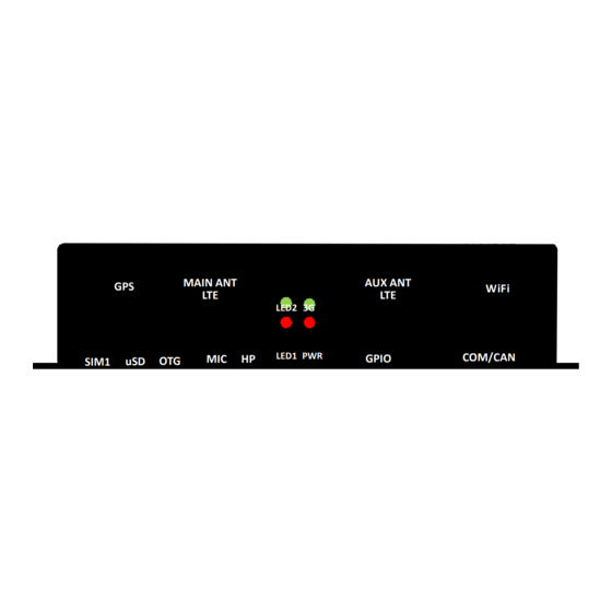
All manuals and user guides at all-guides.com FLEETPC-ARM-300 Series 3.16 There are 4x LEDs at the FLEETPC-ARM-300 front panel: LED2 3G LED1 PWR ... -
Page 42: Keypad Connector
All manuals and user guides at all-guides.com FLEETPC-ARM-300 Series 3.17 Keypad Connector The SW1 keypad connector provides several IO pins connected directly to iMX6 CPU. These pins can be used for Android function keys, for general GPIOs in Android or Linux, or for external interrupt to iMX6 CPU. -
Page 43: Microsd Connector
All manuals and user guides at all-guides.com FLEETPC-ARM-300 Series 3.18 MicroSD Connector The microSD host connector is an industrial standard connector and has the following specification: SD Host Controller Standard Specification version 3.0 ... -
Page 44: Bm Connectors (Firmware Update)
All manuals and user guides at all-guides.com FLEETPC-ARM-300 Series 3.19 BM Connectors (Firmware Update) The CN32 connector is used to select FLEETPC-ARM-300 mode: Normal Operation mode or Firmware Download mode. The Firmware Download mode is for Android/Linux OS update only. If you would like to update your application software, do not use this Firmware Update function. -
Page 45: Other Functions
All manuals and user guides at all-guides.com FLEETPC-ARM-300 Series 3.20 Other functions The other additional functions on FLEETPC-ARM-300 include: Tact Switch SW3 is a tact switch connected directly to iMX6 cpu pin. The GPIO_SW (in below schematic) is connected to iMX6 pad name: CSI0_VSYNC (ball name N2). -
Page 46: Outline Drawing
All manuals and user guides at all-guides.com FLEETPC-ARM-300 Series 4 Outline Drawing FLEETPC-ARM-300 aluminum enclosure outline drawing (cross section): unit: mm 41.7 13.5 ... -
Page 47: Electrical Specifications
All manuals and user guides at all-guides.com FLEETPC-ARM-300 Series 5 Electrical Specifications Absolute Maximum Ratings Unit Note Main Power Supply (DC-IN) 8.55 37.8 Operating Temperature FLEETPC- Operating Range: Unit... - Page 48 All manuals and user guides at all-guides.com VPG300 Series Reference Manual Appendix A: GPIO Photo-Coupler Spec Features: • Gurrent transfer ratio (GTR:MIN.50% at IF =5mA ,VGE =SV) • Highisolation valtage between input and output (Viso=SOOO • Gompact dual-in-line package EL817*:1-channel...
- Page 49 All manuals and user guides at all-guides.com FLEETPC-ARM-300 Series AC for 1 minute, R.H= 60%RH -Isolation voltage shall be measured using the following method. Short between anode and cathode on the primary side and between collector, emitter and base secondary side.
- Page 50 All manuals and user guides at all-guides.com FLEETPC-ARM-300 Series Appendix B: UART/CAN Photo-Coupler Spec Schematic Features • High speed 1OMbiVs • Guaranteed performance from -40 Pin Gonfiguration •...
- Page 51 All manuals and user guides at all-guides.com FLEETPC-ARM-300 Series Electrical Characteristics (T -40 to SS unless specified otherwise) Max. Unit Parameter Symbol Min. Typ. Condition Forward voltage 1.45 IF = 10mA ...
- Page 52 All manuals and user guides at all-guides.com FLEETPC-ARM-300 Series Switching Characteristics (Ta=-40 to 85 IF=7.5mA unless specified otherwise) "C, Vcc=5V, Max. Unit Parameter Symbol Typ. Condition Propagation delay time to outpulHigh 15pFI AL=35001 TPHL level* TA=25"C...
- Page 53 All manuals and user guides at all-guides.com FLEETPC-ARM-300 Series cꞏ Appendix DC-IN Matina Connector Specifications 0225\0225-06XX 3.5 7.0 10.5 14.0 17.5 24.5 31.5 35.0 38.5 21.0 28.0 42.0 7.7 l 14.7 17.2 21.7 25.2 28.7 32.2...
- Page 54 All manuals and user guides at all-guides.com FLEETPC-ARM-300 Series over 150 LII'F DIVG. DATE UNITSI SHEET/OFI 14.05.29 OTES 2: NOI'TI'\ol cfmen'!S...on > WE:t lotet Pitch Toleranees Tohw-onces CHK. DATE SCALEI RoHS complionce :t;0 0<11< =30 o-30 :1:0.25 APP.
- Page 55 All manuals and user guides at all-guides.com FLEETPC-ARM-300 Series Appendix D: DC-IN Connector Specification FilE 0225\0225-16X XTH V=U+l 1.40 P.C. LAYOUT 1.40 V=U+ U-J.SO DINJ<LE 0225-1 J.5 7.0 10.5 14.0...
- Page 56 All manuals and user guides at all-guides.com FLEETPC-ARM-300 Series Appendix E: 102 (GPIO) Mating Connector Specification FILE 0156\0156-2AXX 14.0 1 21.0 24.5 28.0 31.5 35.0 10.54 21.04 24.5 28.04J1.5 J5.04IJB.54...
- Page 57 All manuals and user guides at all-guides.com FLEETPC-ARM-300 Series Appendix F: 102 (GPIO) Connector Specification FilE 01 56\01 56-28XX U=3.50x(P/2-1) NOTES: 1.Rating:150V (UL) (VOE) 320V 10A ...
Need help?
Do you have a question about the FLEETPC-ARM-300 Series and is the answer not in the manual?
Questions and answers