Table of Contents
Advertisement
Advertisement
Table of Contents

Subscribe to Our Youtube Channel
Related Manuals for i4Technology BugHunter Professional BH-04


Summary of Contents for i4Technology BugHunter Professional BH-04
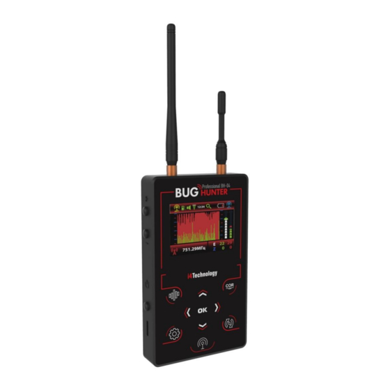
- Page 1 тм RF signal detector BugHunter Professional BH-04 User manual...
-
Page 2: Table Of Contents
CONTENTS Introduction Specification and operation Application area Technical features Device components Internal design and operation Intended use Operating restrictions Before operating Intended usage Technical maintenance Troubleshooting Packaging and transportation... - Page 3 The User Manual includes key features, construction, operating principle, rules of operation (intended use, technical maintenance, repair process, storage, and transportation) of "RF signal detector BugHunter Professional BH-04" (hereafter referred to as the Product). The Product is a device intended to detect radio transmitters in close proximity such as wireless "bugs", wireless microphones, wireless spy cams, portable radio sets, working cellphones, signal suppressors, etc.
-
Page 4: Specification And Operation
Specification and operation The purpose and application area. 1.1.1 The Product allows users to monitor the radio signal strength at a frequency range of 10-8000 MHz and it can also be used to detect nearby field radio transmitters such as wireless "spy bugs", wireless microphones, wireless spy cams, portable radio sets, working cellphones, signal suppressors, etc. -
Page 5: Device Components
Device components. Table 2 № Description Quantity. RF signal detector BugHunter Professional BH-04 Antenna 10-2400 MHz (ANT1) Antenna 2400-8000 MHz (ANT2) Charger 5V 1A Cable mini USB Headphones Shipping box User manual Internal design and operating. 1.4.1 The Product is a portable device that has an autonomous power supply. -
Page 6: Intended Use
1.4.2 Operating principle is based on measuring electric field power via broadband detector. The Prod- uct has two independent high-sensitivity measurement channels (10-2400 MHz and 2400-8000 MHz) to cover the entire possible frequency range where wireless "spy bugs" can be detected; a frequency counter to measure periodic signal frequency;... - Page 7 Then the device switches to the "Search" mode and the screen will look like in Fig.4. Fig.4 – Screen in the "Search" mode To turn the device off, press and hold the button "item 8" for 2 seconds in Fig.2. 2.3.2 Operating modes –...
- Page 8 Fig.6 - Notification in the "Security" mode While changing the modes (by pressing this button ), the notification (Fig.7) appears on the screen for 2 seconds. After it, the device will switch to the "Search" mode. Fig.7 - Notification of switching to the "Search" mode 2.3.2.2 "Search"...
- Page 9 the right part of the graph, while the values are moving to the left, becoming obsolete. Thus, graphs show the changing of the radio environment over time. These graphs are the main means used to search for "spy bugs" via the visual assessment of the signal level and its change as the Product ap- proaches/moves away from the transmission source.
- Page 10 transmission sources while searching. 2.3.2.2.3 Sensitivity and vibrate-mode indication engagement threshold adjustment. You will need to adjust the device sensitivity within the searching process (scale item 6 in Fig.8) and needed) the vibrate-mode indication engagement threshold (scale item 7 in Fig.8). To select the scale use buttons (in order to confirm selection press and hold the button for 2 seconds, with that the selected...
- Page 11 2.3.2.2.7 Use of probing signal. Special probing sound signal can be used in the Product. To activate this function near the intended place of installation of the transmitting device, you must press the button ; the Product will beep (while pressing the button the Product switches to the mode of constant probing signal generation, which is turned off by pressing the same button again).
- Page 12 Fig.9 - Signal strength level increasing when approaching an analog transmitter -If the signal is periodic, the device will display its frequency in MHz. -If there is a strong enough and permanent enough signal level all over the room, it may mean that there is a powerful external source of radio transmission nearby (cell phone tower, strong Wi-Fi access points in the next rooms, etc).
- Page 13 Fig. 11 – The screen in the "Oscilloscope" mode The main purpose of the oscillogram is to inform the user about the form of the radio signal and the nature of its change over time in order to identify the type of transmitter. 2.3.2.3.2 Measurement channel selection.
- Page 14 When switched into "security" mode, the device assesses its surrounding radio environment and memorizes the signal level. Then the device screen turns off. If some new source of signal appears, a cell phone turns on to transmit data or a "spy bug" activates after a long pause in data transmission, etc, the de- vice will alarm you about this - the screen will turn on, the device will vibrate and produce a sound in ac- cordance with current Product settings.
- Page 15 pressing . The time setting screen appears as per Fig.15: Fig.15 – Time settings Select hours or minutes by pressing the buttons or change values by pressing the buttons if necessary. Press to save settings and return to the main menu. To exit without saving the settings, press 2.3.3.3 Brightness.
- Page 16 2.3.3.5 "Security" mode settings. While in the main menu (Fig.13), select "Security mode" by pressing the buttons and confirm the selection by pressing . A sub-menu will appear (Fig.18): Fig.18 – "Security" mode settings This group of parameters determines the need for alarm engagement (and its registration in the logbook) when certain events occur.
- Page 17 Fig.20 – The inclusion of separately selected protocols in the list of alarm events Being in this sub-menu, you can select and activate (or deactivate) separate data transfer protocols by press- . Activated protocols are highlighted in red. 2.3.3.5.4 Duration. This is the setting for the minimum event duration, the exceeding of which triggers an alarm.
- Page 18 selection by pressing , then the selected parameter will be highlighted in red. By pressing , the users can re- turn to the main menu to continue adjustment or they can exit to the operation mode by pressing Note. In the "Security" mode, this setting is ignored. 2.3.3.7 Auto-shutdown time setting While in the main menu Fig.13, select the"Auto-shutdown"...
-
Page 19: Technical Maintenance
Fig.25 – Report (alarm logbook) Attention! In the log-viewing mode, using the product in the main operation modes ("Search", "Oscillo- scope", "Security") is impossible! Attention! After the file is generated, the internal alarm logbook will be cleared when connecting a new file with new data to a PC. -
Page 20: Packaging And Transportation
center 5. Package and transportation. Every Product in the delivery set (see Table 2) is packaged in an individual corrugated cardboard box. Mov- ing the contents of the box is not allowed. Packaged products can be transported by train or by trucks (in covered trucks or containers) or by air transport in pressurized modules.
Need help?
Do you have a question about the BugHunter Professional BH-04 and is the answer not in the manual?
Questions and answers