Table of Contents
Advertisement
Quick Links
Installation Instructions
Commercial Hot Water Systems
The ONLY suitable flue parts are certified Rheem coaxial flue components
•
Unless a certified Rheem coaxial flue system, venting to the outside through a certified Rheem
terminal, is installed in accordance with the Installation Instructions.
•
If a loud continued vibration occurs during operation
This water heater must be installed and serviced by a qualified person.
Owner's Guide
and
Rheem Multipak
INSTALLER:
carrying the following label:
DO NOT use any other type of flue parts.
Carefully follow the Installation Instructions.
OPERATOR:
DO NOT OPERATE THIS WATER HEATER:
Please leave this guide with a responsible officer.
®
Advertisement
Table of Contents

Related Manuals for Rheem Multipak MPE02


Summary of Contents for Rheem Multipak MPE02
- Page 1 OPERATOR: DO NOT OPERATE THIS WATER HEATER: • Unless a certified Rheem coaxial flue system, venting to the outside through a certified Rheem terminal, is installed in accordance with the Installation Instructions. • If a loud continued vibration occurs during operation This water heater must be installed and serviced by a qualified person.
- Page 2 Rheem Australia Pty Ltd and Rheem New Zealand Limited are the suppliers of the Rheem range of continuous flow gas water heaters, manufactured in Japan by Paloma Co., Ltd., a world leader in water heater technology and manufacture.
-
Page 3: Table Of Contents
Rheem warranty. We recommend you read pages 7 to 17, and the terms of the Rheem warranty on pages 4 to 6. The other pages are intended for the installer but may be of interest. -
Page 4: Rheem Continuous Flow Gas Water Heater Warranty - Australia Only
The decision of whether to repair or replace a faulty component is at Rheem’s sole discretion. If you require a call out and we find that the fault is not covered by the Rheem warranty, you are responsible for our standard call out charge. If you wish to have the relevant component repaired or replaced by Rheem, that service will be at your cost. - Page 5 If the water heater is not sized to supply the hot water demand in accordance with the guidelines in the Rheem water heater literature, any resultant fault will not be covered by the Rheem warranty.
- Page 6 You are also entitled to have the goods repaired or replaced if the goods fail to be of acceptable quality and the failure does not amount to a major failure. The Rheem warranty (set out above) is in addition to any rights and remedies that you may have under the Australian Consumer Law.
-
Page 7: Safety And Warnings
The Rheem warranty may not cover faults if safety devices or the relief valve are tampered with or if the installation is not in accordance with these instructions. - Page 8 ABOUT YOUR WATER HEATER • Do not use Propane / Butane gas mixtures in a Propane model. A Propane model is designed to operate on Propane only. The use of Propane / Butane mixture, such as automotive LP gas fuel, in a Propane model is unsafe and can cause damage to the water heater.
-
Page 9: About Your Water Heater
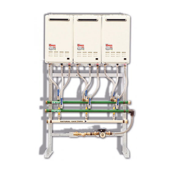
ABOUT YOUR WATER HEATER The Rheem Multipak is a bank of two, three, four, five or six continuous flow water heaters factory manifolded in parallel. All components are factory assembled on a lightweight frame suitable for either wall or optional floor mounting. - Page 10 Note: The preset outlet temperature setting of this water heater cannot be adjusted by the householder. The setting can only be adjusted by the installer, Rheem Service or their nearest Accredited maximum recommended Service Agent. supply temperature to...
- Page 11 Warning: For continued safety of this water heater it must be installed, operated and maintained in accordance with the Owner’s Guide and Installation Instructions. The Rheem warranty may not cover faults if relief valves or other safety devices are tampered with or if the installation is not in accordance with these instructions.
- Page 12 ABOUT YOUR WATER HEATER PRECAUTIONS Where damage to property can occur in the event of the water heater leaking, the water heater must be installed over a safe tray. Construction, installation and draining of a safe tray must comply with AS/NZS 3500.4 and all local codes and regulatory authority requirements.
- Page 13 ABOUT YOUR WATER HEATER Warning: Servicing of a water heater must only be carried out by qualified personnel. Phone Rheem Service or their nearest Accredited Service Agent. The annual service includes the following actions: • Check and if necessary adjust the gas pressure.
- Page 14 The frost protection system will be rendered inoperable if electrical power is not available at the water heater. Damage caused by freezing due to the unavailability of power at the water heater is not covered by the Rheem warranty (refer to “Terms of the Rheem Warranty”...
-
Page 15: Water Supplies
In a corrosive water supply, the water can attack copper parts and cause them to fail. Where the saturation index is less than –1.0, the water is very corrosive and the Rheem warranty does not apply to a copper heat exchanger in a continuous flow water heater. -
Page 16: Save A Service Call
Check the items below before making a service call. You will be charged for attending to any condition or fault, which is not related to manufacture or failure of a part (refer to “Terms of the Rheem Warranty” page 6). - Page 17 If the error code persists, take note of the numerical code, turn off the hot tap and turn off the controller(s). Phone Rheem Service or their nearest Accredited Service Agent to arrange for inspection.
-
Page 18: Multipak - Technical Specifications
Optional circulating pump complete with valves and fittings to AS3500.4 SKID PACKAGE COMPRISING OF: • ‘Rheem’ water heaters, cold water, hot water, natural gas / LPG manifolds and options are fully assembled and all mounted on a Galvabond Steel frame. Package is ready for site installation. •... - Page 19 CIRCULATION PUMP OPTION Optional Circulating Pump Package comprising of: • A 25mm in-line circulating pump in cast bronze designed for secondary hot water circulation. 240V/1Ph/50Hz; IP44 canned motor with three speed setting option. • Pump is provided with unions, in-line strainer, isolation ball valves, check valve and integrated into the system with required plumbing fittings.
-
Page 20: Installation - Water Heater
INSTALLATION – WATER HEATER THIS WATER HEATER IS FOR OUTDOOR OR INDOOR INSTALLATION, MODEL DEPENDANT. THIS WATER HEATER IS NOT SUITABLE FOR POOL HEATING. Check the water heater is suitable for the gas type available. (refer to the rating label on the water heater) INSTALLATION STANDARDS The water heater must be installed: •... - Page 21 INDOOR INSTALLATION VENTILATION This water heater is to be installed with a Rheem coaxial flue system. The kit enables a room sealed installation, drawing air for combustion from outside of the building. The ventilation of a room or an enclosure such as a cupboard, where the water heater is installed must comply with the requirements of AS/NZS 5601.1, as applicable under local regulations.
- Page 22 Damage to the water heater caused by freezing of the pipe work to or from the water heater is not covered under the Rheem warranty. Refer to AS/NZS 3500.4 for precautions to be taken for installations in frost prone areas. The water heater is not suitable for installation in areas where the ambient temperature falls below -20°C (including wind chill factor).
- Page 23 A temperature limiting device cannot be installed in circulated hot water flow and return pipe work, unless it is specifically designed to do so, such as the Rheem Guardian warm water system. The tempered water from a temperature limiting device cannot be circulated. Where a circulated hot water flow and return system is required in a building, a temperature limiting device can only be installed on a dead leg, branching off the circulated hot water flow and return pipe.
-
Page 24: Connections - Plumbing
Warning: Always isolate the water heater before pressure testing the gas supply system. Disconnect the water heater after the isolation valve to prevent the risk of serious damage to the gas control. The Rheem warranty does not cover damage of any nature resulting from failure to observe this precaution. Refer to rating... -
Page 25: Flueing
A sealing gasket is located at one end of the inner flue. Check all flue components to ensure the gasket is in place and properly seated. DO NOT install if any gaskets are missing. Contact Rheem Service or their nearest... - Page 26 INSTALLATION - WATER HEATER COMPONENTS A complete flue system is comprised from the following components. horizontal flue terminal trim ring (PN 295146) (PN 295125) Flue Outlet condensate trap assy condensate tube assy (PN AS33121006) (PN AS33121007) One per system required One per heater required 90°...
- Page 27 INSTALLATION – WATER HEATER FLUE TERMINAL LOCATION The water heater must be located to ensure that the location of the flue terminal complies with the requirements of AS/NZS 5601.1, as applicable under local regulations. As a guide the following requirements are extracted from the Gas Installations Standard.
- Page 28 Failure to discharge build-up of condensate in flues could allow acidic flue gas condensate to enter into the water heater flue-way, causing premature failure of the water heater. Any resultant faults will not be covered by the Rheem warranty. Note: A horizontal run of flue connecting directly to a Horizontal Flue Terminal must have a gradient downward...
- Page 29 CFWH. Identify the number of condensate trap kits required (Rheem part number AS3312006). One (1) kit is required for wall mount and floor mount systems. Two (2) kits are required for back to back systems.
- Page 30 Warning: Failure to fill with water may cause flue gasses to escape through the condensate trap. Check regularly to ensure the condensate trap is filled with water, replenishing when required. Warning: Do not remove or tamper with the condensate trap. Only the end tube of the condensate trap may be cut to aid in directing the discharge point.
- Page 31 INSTALLATION – WATER HEATER HORIZONTAL FLUE RUNS There are several basic installation requirements which must be followed for a flue installation incorporating horizontal flue runs. Failure to observe these precautions can lead to the premature failure of the flue system and / or water heater.
- Page 32 Figure 20- Typical Installation Horizontal Terminal with Multiple Vertical and Horizontal Sections Figure 21- Typical Installation Through the Roof Figure 22- Typical Installation Vertical Terminal Flueing with Vertical Sections with Vertical and Horizontal Sections...
- Page 33 INSTALLATION – WATER HEATER HORIZONTAL FLUE INSTALLATION Horizontal Flueing – Directly Behind Water Heater This method of flue installation is used where the secondary flue is to penetrate and terminate immediately behind the wall on which the water heater is mounted. Do not remove the plastic film from the flue outlet of water heater prior to this type of flue installation, to prevent debris from the drilling operation entering the water heater flue outlet.
- Page 34 Connect the horizontal terminal (PN295146) and 300mm straight length (PN 295152) into the hole it the wall. Fit a trim ring over the last section of flue. Secure each flue component using the sheet metal screws provided. Connect the 90° Elbow (PN 295147) to the water heater flue outlet so it is orientated behind the water heater.
- Page 35 INSTALLATION – WATER HEATER Horizontal Flueing – Extended Flue Run Notes: • Ensure each flue component is fully engaged and the rubber seal on the inner duct is well seated at each joint. • Each flue component is supplied with screws to connect to the adjacent flue component. The screws are located in a bag taped to the outside of the flue component.
- Page 36 Carefully remove the template inserted as the middle pages of this installation instructions booklet. Cut along the middle of the bold circle marked “Cut Line”. Align the top of the circular template with the mark on the wall. It may be convenient to tape the template to the wall. ...
- Page 37 INSTALLATION – WATER HEATER Once the flue is assembled and penetrating the wall, install the Horizontal Terminal and secure the termination to the flue using the sheet metal screws provided. Note: If the flue terminal position is more than 1800 mm above a safe working surface, then suitable equipment will be required to enable safe access to fit the flue terminal.
- Page 38 Vertical Flue Installation Suitable flashing (not supplied) is required to waterproof the roof penetration. Notes: • Ensure each flue component is fully engaged and the rubber seal on the inner duct is well seated at each joint. • Each flue component is supplied with screws to connect to the adjacent flue component. The screws are located in a bag taped to the outside of the flue component.
- Page 39 INSTALLATION – WATER HEATER Fix a Wall Bracket after each transition to a vertical run. This is to prevent vertical loading on the elbows and offsets. Support vertical sections of flue at a distance no greater than 2 m using a Wall Bracket (PN 295128). Note: The Wall Bracket can be used to support vertical sections of flue from a ceiling by rotating the legs through 90°.
- Page 40 MULTIPLE WATER HEATER FLUE INSTALLATION Where multiple water heaters are installed, each water heater must be individually flued to the outside. A common flue system MUST NOT be used. For a multiple unit installation, the water heater is certified for installation with zero clearance between adjacent water heaters.
- Page 41 INSTALLATION – WATER HEATER MULTIPLE WATER HEATER CONDENSATE TRAP AND CONDENSATE DRAIN LINE INSTALLATION Depending upon the type of installation, it may be necessary to install a condensate trap and condensate drain line to each water heater. Refer to “Draining the Condensate” on page 28.
- Page 42 Warning: Failure to fill with water may cause flue gasses to escape through the condensate trap. The condensate trap should be regularly checked to ensure it is filled with water, replenishing when required. Notes: AS/NZS 3500.4 is used as a guide in preparing the following drainage recommendations. •...
-
Page 43: Connections - Electrical
INSTALLATION – WATER HEATER CONNECTIONS - ELECTRICAL All electrical work and permanent wiring must be carried out by a qualified person and in accordance with the Wiring Rules AS/NZS 3000 and all local codes and regulatory authority requirements. The water heater will only operate on a sine wave at 50 Hz. Devices generating a square wave cannot be used to supply power to the water heater. - Page 44 MULTIPAK INTERNAL (MPI02-MPI06) – GENERAL ARRANGEMENT...
- Page 45 MULTIPAK EXTERNAL (MPE02-MPE06) – GENERAL ARRANGEMENT...
-
Page 46: Commissioning
COMMISSIONING INITIAL CHECKS 1. Check that the power supply to the system is switched OFF. 2. Check that an adequate water supply is available to the hot water system. Water supply pressure shall not exceed 800kPa. 3. OPEN cold water inlet valve, hot water outlet valve, (and hot water return valve with pump option only) Check all individual water heater isolation valves are OPEN;... - Page 47 COMMISSIONING GAS INLET TEST POINT PRESSURE To check the gas inlet pressure, select the CFWH at the furthest point in the manifold as the test unit: Ensure the burners are not operating, by turning off the power to each CFWH. Close the gas isolation valve at the gas inlet to the CFWH.
- Page 48 COMMISSIONING Warning: The removal of the front panel will expose 240 Volt wiring. Take care not to touch wiring terminals. WASHER TEST POINT MINIMUM TEST POINT GAS PRESSURE ORIFICE TEST Refer to the rating label on the water heater for the minimum POINT test point gas pressure.
- Page 49 COMMISSIONING Notes: • If the burners extinguish and error code 11 or 12 starts to flash on the LED display: • release the MIN and adjuster buttons • close the CFWH isolation valve • clear the error code (refer to “Clearing Error Code”...
- Page 50 COMMISSIONING PRESET OUTLET TEMPERATURE SETTING The factory preset outlet temperature setting of the water heater is: • 60°C as part of a Multipak system • 50°C as part of a Mulitpak /50 system It is usually not necessary to check or adjust the factory preset outlet temperature setting of the water heater, unless the customer or application has a particular requirement for this to be done.
- Page 51 COMMISSIONING TO CHECK OR ADJUST THE PRESET OUTLET TEMPERATURE SETTING The temperature settings will be displayed on the LED display. The preset outlet temperature settings are: • 872/862 series 38°C, 40°C, 42°C, 43°C, 45°C, 50°C, 55°C, 60°C, 65°C, 70°C, 75°C, 82°C It is necessary to have the electrical supply to the water heater switched on during stages of checking or adjusting the preset outlet temperature setting procedure.
- Page 52 • Damage caused by freezing due to the unavailability of power at the water heater is not covered by the Rheem warranty (refer to “Terms of the Rheem Warranty” on page 4). • If the power has been switched off to the water heater and there is a risk of freezing, then it is necessary to drain the water heater (refer to “Draining the Water Heater”...
- Page 53 Continue to check strainers on a Quarterly basis until they inspect clean. Thereafter check every six (6) months. Re-instate Multipak by repeating steps Initial checks on page 46 Fill in Multipak Commissioning Sheet (Refer Page 54). Rheem Multipak can now be left on line.
- Page 54 COMMISSIONING MULTIPAK – COMMISSIONING SHEET Customer : Project and Address: Package Details: Installation Comments Overall Installation? Ventilation Requirements? Compliance to AS/NZS5601.1 is mandatory Co-axial Flueing Compliance to AS/NZS5601.1 is mandatory Refer: Owner's Guide and Installation Instructions Model 627 Continuous Flow Gas Outdoor Water Heater 872 Series Electronic Continuous Flow Gas Indoor Water Heater 862...
- Page 55 Check for minimum 140KPa water supply pressure available. Failure • Check CFWH strainers for cleanliness • RECFWH Refer to Rheem Owner’s Guide and Installation Instructions for Fault additional Information • Check pump operation (if fitted) as per commissioning list - item Long delay Optional •...
- Page 56 COMMISSIONING MULTIPAK – OPTIONAL CIRCULATING PUMP SUCTION STRAINER CLEANING Turn Off the power supply to the circulating pump. Isolate the pump upstream valve. Remove the pump upstream strainer assembly. Clean and refit. Re-instate the pump upstream valves to open position. Follow the secondary pump commissioning start-up instructions 7, 8 and 9 as stated before.
- Page 57 This page is intentionally blank...
- Page 58 This page is intentionally blank...
- Page 59 This page is intentionally blank...
- Page 60 RHEEM AUSTRALIA PTY LTD FOR SERVICE TELEPHONE A.B.N. 21 098 823 511 131 031 AUSTRALIA www.rheem.com.au 0800 657 335 NEW ZEALAND AQ0901140-A August 2021 REV A 210806 EPCR:...
Need help?
Do you have a question about the Multipak MPE02 and is the answer not in the manual?
Questions and answers