Advertisement
Quick Links
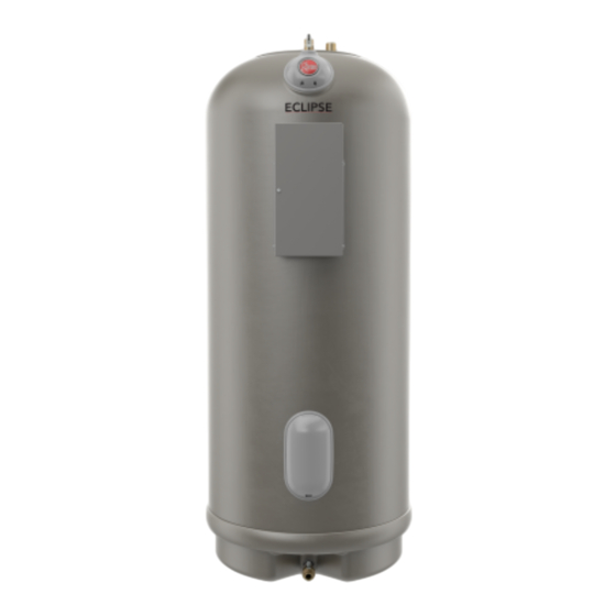
Light Duty Commercial Electric
Water Heaters
Use & Care Manual
With Installation Instructions for the Installer
Double Element Models,
75, 85, 105 Gallon
The purpose of this manual is twofold:
one, to provide the installer with the
basic directions and recommendations
for the proper installation and adjustment
of the water heater; and two, for
the owner–operator, to explain the
features, operation, safety precautions,
maintenance and troubleshooting of the
water heater. This manual also includes a
parts list.
It is imperative that all persons who are
expected to install, operate or adjust
this water heater read the instructions
carefully so they may understand how to
perform these operations. If you do not
understand these instructions or any terms
within it, seek professional advice.
Any questions regarding the operation,
maintenance, service or warranty of this
water heater should be directed to the
seller from whom it was purchased. If
additional information is required, refer to
the warranty.
Do not destroy this manual. Please read
carefully and keep in a safe place for
future reference.
Recognize this symbol as an
!
indication of Important Safety
Information!
California Proposition
!
65 Warning:
This product contains chemicals
known to the State of California to
cause cancer, birth defects or other
reproductive harm.
AP23006
Advertisement

Subscribe to Our Youtube Channel
Related Manuals for Rheem MELD85-TB


Summary of Contents for Rheem MELD85-TB
- Page 1 Use & Care Manual With Installation Instructions for the Installer Light Duty Commercial Electric Water Heaters Double Element Models, 75, 85, 105 Gallon The purpose of this manual is twofold: one, to provide the installer with the basic directions and recommendations for the proper installation and adjustment of the water heater;...
-
Page 2: Table Of Contents
FOR YOUR RECORDS Safety Information Safety Precautions ..3, 4 Write the model, serial numbers, and installation details on the back cover of the manual. This information is located on the rating plate (silver label) on the unit. -
Page 3: Important Safety Information
IMPORTANT SAFETY INFORMATION. READ ALL INSTRUCTIONS BEFORE USING. DANGER! WATER TEMPERATURE SETTING Safety and energy conservation are factors to be considered when selecting the water temperature setting of water heater’s thermostat. Water temperatures above 125°F (51°C) can cause severe burns or death from scalding. Be sure to read and follow the warnings outlined on the label pictured below. -
Page 4: Safety Precautions
IMPORTANT SAFETY INFORMATION. READ ALL INSTRUCTIONS BEFORE USING. WARNING! For your safety, the information in this manual must be followed to minimize the risk of fire or explosion, electric shock, or to prevent property damage, personal injury, or loss of life. -
Page 5: Installing The Water Heater
Installing the water heater. Local Installation Regulations This water heater must be installed in be weather sealed to the floor, a raised accordance with these instructions, local base, or on a shelf so that seepage cannot codes, utility codes, utility company accumulate under it;... -
Page 6: Thermal Expansion
Installing the water heater. Thermal Expansion Determine if a check valve exists in the and system piping. This rapid pressure inlet water line. Check with your local increase can quickly reach the safety water utility. It may have been installed setting of the relief valve, causing it in the cold water line as a separate back to operate during each heating cycle. -
Page 7: Temperature And Pressure Relief Valve
A new combination temperature and pressure relief valve, complying with the Standard for Relief Valves for Hot Water Supply Systems, ANSI Z21.22, is supplied and must be installed in the opening provided and marked for the purpose on the water heater. No valve of any type should be installed between the relief valve and the tank. -
Page 8: Water Connections
Installing the water heater. Water Supply Connections Refer to the illustration on the The cold water connection and the NOTICE: DO NOT at- tempt to turn any fitting next page for suggested typical temperature and pressure relief connected to the water installation. -
Page 9: Typical Installation
Typical Installation Support the relief valve drain pipe using metal strapping or wire fastened to the Pre-solder 12" minimum structure overhead Cold Inlet Shut stub pipes before installing to unit. Temperature & Pressure Hot Water Outlet Relief Valve Heat Trap 6" Minimum Seal Ring (Inside nut) -
Page 10: Electrical Connections
Installing the water heater. Electrical Connections DO NOT turn on the electrical A separate branch circuit with copper The branch circuit wiring should include either: supply or operate this water conductors, over current protective device heater unless it is completely full and suitable disconnecting means must be Metallic conduit or metallic of water. -
Page 11: Wiring Diagram
Branch Circuit Sizing and Wire Size Guide Single Phase Wiring Total Recommended Over Current Protection Copper Wire Size AWG Based on NE.C. Water (Fuse or circuit breaker amperage rating) Table 310-16 (75°C) Heater Wattage 208V 240V 277V 415V 480V 208V 240V 277V 415V... -
Page 12: Branch Circuit Sizing
Installing the water heater. Branch Circuit Sizing and Wire Size Guide, For MELD 75, 85, and 105 Models NOTICE: This guide recommends minimum branch circuit sizing and wire size based on National Electric Code. Refer to wiring diagrams in this manual for field wiring connections. 208 Volt Rated Factory Shipped Rating Water Heaters... -
Page 13: Wiring Diagrams
Wiring Diagrams. Fused (208 - 240 Volts) 2 WIRE SIMULTANEOUS 2 WIRE NON-SIMULTANEOUS RED/BLACK SECONDARY BRANCH CIRCUIT BLUE/WHITE BRANCH CIRCUIT TO ELECTRICAL TO ELECTRICAL DISTRIBUTION DISTRIBUTION YELLOW/BLACK PANEL, OFF- PANEL PEAK METER, OR TIMER BLACK/WHITE BROWN/WHITE RED/BLACK BRANCH CIRCUIT BLUE/WHITE TO ELECTRICAL DISTRIBUTION YELLOW/BLACK... -
Page 14: Insulation Blankets
Installing the water heater. Insulation Blankets Insulation blankets, available to the CAUTION: If local codes require the WARNING: If local general public, for external use on electric application of an external insulation codes require external water heaters are not necessary. The blanket to this water heater, pay careful application of insulation purpose of an insulation blanket is to... -
Page 15: Installation Checklist
Installation Checklist A. Water Heater Location Close to area of heated water demand. I ndoors and protected from freezing temperatures. A rea free of flammable vapours. P rovisions made to protect area from water damage. S ufficient room to service heater. B. -
Page 16: Operating The Water Heater
Operating the water heater. Safety Precautions DO turn off power to water heater if If there is any difficulty in it has been subjected to over heating, understanding or following the fire, flood, physical damage. Operating Instructions or the Care and Cleaning section, it is DO NOT turn on water heater unless recommended that a qualified person it is filled with water. - Page 17 If adjustment is necessary… NOTICE: DO NOT use this appliance if any part WARNING: If the water heater has been has been under water. Immediately call a qualified subjected to fire, flood, or physical damage, turn off installer or service agency to replace a flooded water power to water heater, and DO NOT operate the heater.
-
Page 18: Care And Cleaning
Care and cleaning of the water heater. Draining the Water Heater NOTICE: Additional Lift open the handle on the relief Shut off power to the water heater. instructions for draining valve, and leave open. (top center Open a hot water faucet nearest the the unit are located on the fitting on water heater) (some water water heater. -
Page 19: Troubleshooting Tips
Before You Call For Service… Troubleshooting Tips Save time and money! Review the chart on this page first and you may not need to call for service. Problem Possible Causes What to Do Rumbling noise Water conditions in your location Remove and clean the heating elements. -
Page 20: Replacement Parts
Replacement Parts. Key No. Description Dip Tube Grommet, Large Grommet, Small Seal Ring, Large Seal Ring, Small Vacuum Valve Assembly Temperature and Pressure Relief Valve Knock-Out Bracket Screw, #8 x 3/4" Junction Box Cover Screw #8-16 x 5/8" Upper Thermostat Upper Protector Screw, #10-16 x 5/8"... - Page 21 Replacement Parts. 208 - 240 Volts...
- Page 22 Replacement Parts. 277 - 415 - 480 Volt.
-
Page 23: Element Replacement
Element Replacement Instructions 1. Turn off power to the unit. NOTICE: Make sure the threads on the unit are clean. Brush debris off of DANGER: Make certain power threads with a toothbrush if needed. to the water heater is “OFF” before removing any jacket access NOTICE: The elements are unique panel for any reason. -
Page 24: Warranty
Rheem Sales Co. Inc. does not authorize, recommend, or receive any benefit from any claims processing or similar fees charged by others to process warranty claims for any Rheem Sales Co. Inc. water heater or component part(s). Rheem Sales Co. Inc. will not reimburse any party for these, or any other, fees not specifically covered in this Limited Warranty document. - Page 25 Technical Service person you call with the complete model number, the complete serial number, and the date of installation of your water heater in addition to an explanation of your water heater problem. If an exact replacement is not available, Rheem Sales Co. Inc.
-
Page 26: How To Register
Warranty claim documentation should be mailed promptly to Rheem Sales Co. Inc., Warranty Department, Rheem Sales Co. Inc. 800 Interstate Park Drive Montgomery, AL 36109 FOR YOUR RECORDS Owner Information Name Address Plumber / Mechanical Contractor – Installer Information Name... - Page 27 How to Register Your Product: Step 5: Step 3: 1. Enter the fields on the screen 1. Review confirmation page and make any nec- • Warranty Type choices are essary edits. Once verified click Finish. • Standard Notice the disclaimer at the bottom that explains •...
-
Page 28: If You Need Service
Date of original installation and dates any service work was performed. e. Details of the problems as you can best describe them. f. List of people, with dates, who have been contacted regarding your problem. Additional service information can be found at www.rheem.com.
Need help?
Do you have a question about the MELD85-TB and is the answer not in the manual?
Questions and answers