
Related Manuals for Time Guard MLB3000


Summary of Contents for Time Guard MLB3000
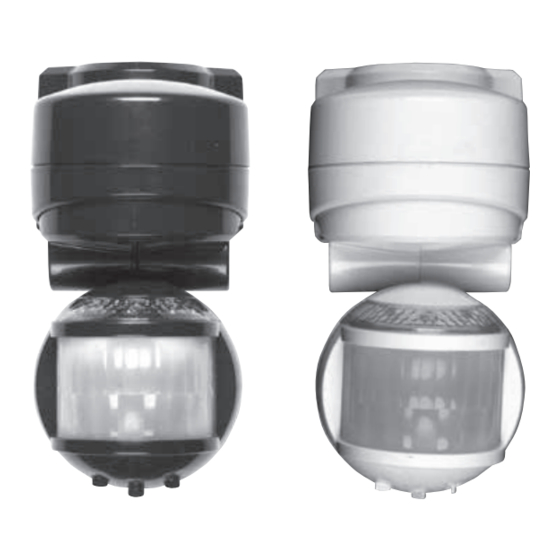
- Page 1 3000W MULTI PIR LIGHT CONTROLLER Cat No. MLB3000 – Black Cat No. MLW3000 – White Installation & Operating Instructions...
- Page 2 Time Dusk/Dawn Override/Holiday Mode Lens Mask Restrict long detection Restrict short detection Restrict RHS detection Restrict LHS detection...
-
Page 3: Top View
TOP VIEW 200º SIDE VIEW 2.5m Less sensitive More sensitive... -
Page 4: General Information
SECTION ONE GENERAL INFORMATION The unit utilises passive infrared technology to detect heat radiation of moving human bodies. Upon detection, the lamp will illuminate for a user-determined time period. An integral daylight sensor ensures night-only operation. PARTS INCLUDED – PIR Sensor unit. –... -
Page 5: Installation
SECTION THREE INSTALLATION After choosing a suitable location (see previous section) install the unit as follows: *** IMPORTANT *** Switch off the electricity at the fuse box by removing the relevant fuse or switching off the circuit breaker before proceeding with the installation. Remove the wiring box cover by unscrewing the retaining screw (diagram F) and with a screwdriver gently push down and ease out. -
Page 6: Operation And Testing
CONNECTION DIAGRAM Isolation Switch Load Mains Supply SECTION FOUR OPERATION AND TESTING WALK TEST PROCEDURE The sensor will rotate from left to right, and tilt forward or backward. Adjust the sensor to point in the required direction (see diagram B). The unit can be set up in daylight or at night. - Page 7 The TIME setting controls how long the unit remains illuminated following activation and after all motion ceases. (See diagram G. the time adjustment knob is indicated by the ‘Clock’ symbol). The minimum time (fully anti-clockwise) is approx. 5 seconds, whilst the maximum time (fully clockwise) is approx.
-
Page 8: Holiday Mode
HOLIDAY MODE – SINGLE LED FLASHING The benefit of Holiday Mode is that the user can program the unit automatically illuminate for a certain time, (1 – 8 hours) each night. At dusk the unit will illuminate for this set period after which it will extinguish. -
Page 9: Troubleshooting Guide
SECTION SIX TROUBLESHOOTING GUIDE SOLUTION PROBLEM The unit may be suffering from false activation. Cover the o Lamp stays ON all the time sensor lens completely with a thick cloth. This will prevent at night. the sensor from "seeing" anything. If the unit now switches off after the set time duration and does not re-activate, this indicates that the problem was caused by false activation. - Page 10 PROBLEM SOLUTION o Unit activates during The level of ambient light in the area may be too dark the daytime for the current DUSK setting. During daylight, adjust the DUSK control slightly anti-clockwise. When the lamp load extinguishes, enter the detection area. If the PIR still activates, the setting is still too high.
- Page 11 Place this edge against wall and use diagram to estimate incoming cable length 75mm (3”) NOT TO SCALE 25mm (1”) INCOMING WIRE TEMPLATE Use this diagram to estimate incoming cable length...
- Page 12 For assistance with the product please contact:- HELPLINE 020-8450-0515 or email helpline@timeguard.com For a product brochure please contact: Timeguard Ltd. Victory Park, 400 Edgware Road, London NW2 6ND Tel: 020 8452 1112 or email csc@timeguard.com Group company 67-058-308 (Iss.2)
Need help?
Do you have a question about the MLB3000 and is the answer not in the manual?
Questions and answers