Table of Contents
Advertisement
Quick Links
Advertisement
Table of Contents

Related Manuals for ABB ACS1000


Summary of Contents for ABB ACS1000
- Page 1 — SYSTEM DRIVES ACS1000 water-cooled User manual OWNING ORGANIZATION DATE STATUS SECURITY LEVEL ABB Switzerland Ltd. 2021-11-17 Approved Public DOCUMENT KIND DOCUMENT ID. REV. LANG. PAGE User manual 3BHS213400 E01 1/166 © Copyright 2009 ABB All rights reserved.
- Page 2 This document contains information about one or more ABB products and may include a description of or a reference to one or more standards that are relevant to the ABB products. The presence of any such description of a standard or reference to a standard is not a representation that all of the ABB products referenced in this document include all the features of the described or referenced standard.
-
Page 3: Table Of Contents
CONTENTS — Contents 1. About this manual .................... 13 1.1. Equipment covered by this manual ..............13 1.2. Structure of the user documentation ............. 13 1.3. Terms and abbreviations .................. 14 1.4. Related documents ................... 16 1.5. Target groups and required qualification ............17 1.5.1. - Page 4 CONTENTS 3.7.1. Internal arc classification ............... 46 3.7.2. Power compartment doors ..............46 3.7.3. Associated protection requirement ............47 3.8. Space heaters ....................47 4. Control system ....................49 4.1. Overview ......................49 4.2. Main components ....................50 4.2.1. Local control panel .................. 51 4.2.2.
- Page 5 CONTENTS 7.6. Power cables, ground cables and equipotential bonding conductor ................... 82 7.6.1. Preparing the cable entry, the cable spacers and the cables ....................82 7.6.2. Connecting the cables ................94 7.6.3. Bolted connections ................. 94 7.7. Auxiliary power, control and serial communication cables ......96 7.7.1.
- Page 6 CONTENTS 10.3.2. Actual signals mode ................121 10.3.3. Parameters mode ................128 10.3.4. Functions mode ..................134 10.4. Local and remote control ................136 10.4.1. Local control ................... 136 10.4.2. Remote control ..................137 10.5. Operational commands .................. 138 10.5.1. Setting the direction of rotation ............
- Page 7 Figure 2-2 Drive system overview ................... 27 Figure 2-3 MCB opening timing diagram ..............29 Figure 3-1 ACS1000 water-cooled ................... 31 Figure 3-2 Block diagrams of an ACS1000W with a 12-pulse rectifier (A) and a drive with a 24-pulse rectifier (B) ..............32 Figure 3-3 Drive overview with power supplies ............
- Page 8 FIGURES Figure 5-1 Transporting the cabinet by crane - standard case ......... 65 Figure 5-2 Transporting the cabinet by crane - marine/offshore case ..... 66 Figure 6-1 Leveling the drive ................... 71 Figure 6-2 Location of screw holes in a standard cabinet base and anchor bolt example ......................
- Page 9 FIGURES Figure 9-1 Local operator panel ..................108 Figure 10-1 CDP control panel ..................119 Figure 10-2 Control panel - Actual signals mode ............123 Figure 10-3 Control panel - Parameters mode ............130 Figure 10-4 Control panel - Functions mode ............. 134 Figure 11-1 Device identification ..................
- Page 11 Table 3-1 Braking ratings .......................... 43 Table 3-2 Cabinet dimensions and weight ..................44 Table 3-3 Braking resistor cables ......................44 Table 3-4 ABB arc resistant classes......................46 Table 4-1 IOEC module configuration - analog inputs..............57 Table 4-2 IOEC module configuration - analog outputs ..............57 Table 4-3 IOEC module configuration - digital inputs ..............
-
Page 13: About This Manual
(eg, layout drawings, wiring diagrams, technical data, engineering notes). If information is required beyond the instructions in this manual, refer the matter to ABB. 1.2. Structure of the user documentation The documentation for a standard drive consists of this document and the following project-specific appendices. -
Page 14: Terms And Abbreviations
The following table lists terms and abbreviations you should be familiar with when using this user manual. Some of the terms and abbreviations used in this user manual are unique to ABB and might differ from the normal usage. Table 1-1 Terms and abbreviations... - Page 15 Resistance temperature detector or device The RTD is a temperature sensor where the change in electrical resistance is used to measure the temperature. Safeline ABB synonym for uninterruptable power supply Supervisory signal Indicates the operating condition of a circuit or device. Software...
-
Page 16: Related Documents
ABOUT THIS MANUAL 1.4. Related documents Table 1-2 Maintenance Title Document number ACS1000 preventive maintenance schedule 3BHS855276 E01 Table 1-3 Technical data Title Document number Technical data from DriveSmart (configuration software for medium voltage drives) Configuration software for medium voltage drives... -
Page 17: Target Groups And Required Qualification
Commissioning of the drive must only be performed by qualified and certified ABB personnel. -
Page 18: Maintenance
Use of the drive outside the scope of the specifications is not permitted. Intended equipment use also implies that only spare parts recommended and approved by ABB must be used. Unauthorized modifications and constructional changes of the drive are not permitted. -
Page 19: Quality Certificates And Applicable Standards
1.8. Quality certificates and applicable standards The following certificates and conformity declarations are available with ABB: – ISO 9001 and ISO 14001 certificates stating that ABB Switzerland Ltd has implemented and maintains a management system which fulfills the requirements of the normative standards –... -
Page 20: Identifying The Delivery
ABOUT THIS MANUAL Items covered by delivery Delivery typically comprises the following items: – Drive that is shipped in sea freight or airfreight packaging. – Optional components and cabinets – Set of door keys attached to lifting rail (1 in Fig. 1-1) –... -
Page 21: Important Safety Information
IMPORTANT SAFETY INFORMATION 2. Important safety information Read this material carefully before working on or around the equipment. Failure to do so can result in serious Injury or DEATH! Keep for future reference. 2.1. Safety standards The following industry standards are observed: –... -
Page 22: Product Safety Labels
IMPORTANT SAFETY INFORMATION 2.3. Product safety labels Safety labels are affixed to the drive components to alert personnel of potential hazards when working on the equipment. For more information, see the label placement document for the drive. The instructions on the safety labels must always be followed and the labels must be kept in a perfectly legible condition. -
Page 23: General Safety Instructions
IMPORTANT SAFETY INFORMATION 2.4. General safety instructions Minimize hazards Before energizing the drive: • Remove all foreign objects from the drive • Fasten all internal and external covers securely • Close, lock, and/or bolt all doors • Move the release dial of the door safety switches into the locked position Before working on the drive: •... -
Page 24: The 7 Steps That Save Lives
IMPORTANT SAFETY INFORMATION 2.5. The 7 steps that save lives ABB’s 7 steps that save lives concept is a series of actions that must take place prior to commencing work on or near electrical installations. Prepare for the work: do an on-site risk assessment or job hazard analysis that considers the limits of approach for shock and arc-flash. - Page 25 IMPORTANT SAFETY INFORMATION 4) Verify the absence of operating voltage: always test before you touch! Only use properly rated and inspected voltage detection devices and wear proper PPE identified in step 1: • Test voltage detection device • Test for voltage •...
-
Page 26: Possible Residual Risks
IMPORTANT SAFETY INFORMATION 2.6. Possible residual risks Residual risks must be considered by the drive system integrator and/or plant owner when assessing the hazards of the equipment to personnel. The following risks can pose a hazard to drive system personnel: Electric power equipment generates electro-magnetic fields which can cause a hazard to people with metal implants and / or a pacemaker. -
Page 27: Main Circuit Breaker Protection Device
IMPORTANT SAFETY INFORMATION 2.7. Main circuit breaker protection device The main circuit breaker (MCB) is a major protection device of the drive. If a serious fault occurs in the drive, the MCB must disconnect the main power supply to the drive immediately. -
Page 28: Safety And Protection Requirements
2.7.1. Safety and protection requirements For safety and protection reasons, the MCB must meet the stipulated minimum requirements of the specifications of ABB MV Drives. It is the system integrator's responsibility to ensure that the minimum requirements are met. The minimum requirements for the MCB are stated in this note and in the respective MCB specifications, which are available for each medium voltage drive from ABB. -
Page 29: Maintenance Recommendation
3) No further damage to the drive 4) No hazard to personnel 5) Maximum protection trip time 6) Maximum safety trip time In order to meet the stipulated safety requirements, ABB recommends one of the following: – MCB is equipped with 2 independent opening coils –... -
Page 31: Power Electronics And Cabinet Features
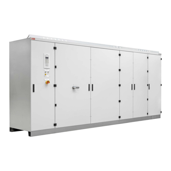
Available main and auxiliary power configurations – Power electronic components of the drive – Cooling system – Cabinet features such as the grounding switch and the electro-mechanical door interlock Figure 3-1 ACS1000 water-cooled PRODUCT DOCUMENT KIND DOCUMENT ID. REV. LANG. PAGE ACS1000W... -
Page 32: Main Components Of The Drive System
POWER ELECTRONICS AND CABINET FEATURES 3.2. Main components of the drive system Figure 3-2 Block diagrams of an ACS1000W with a 12-pulse rectifier (A) and a drive with a 24-pulse rectifier (B) 1) Medium voltage switchgear including main 5) DC link circuit breaker and transformer protection 6) Inverter 2) Transformer... -
Page 33: Power Supply Configurations
POWER ELECTRONICS AND CABINET FEATURES 3.3. Power supply configurations The drive requires 2 independent power supplies: – Main power supply for the power electronic components – Auxiliary power supply for the control and cooling system Figure 3-3 Drive overview with power supplies 1) Auxiliary power supply 8) MCB 2) ACS1000W... -
Page 34: Auxiliary Power Supply Configurations
POWER ELECTRONICS AND CABINET FEATURES 3.3.2. Auxiliary power supply configurations The total auxiliary power demand of the drive includes: – Auxiliary power for the cooling system – Auxiliary power for the control hardware and the gate units which are used to trigger the power semiconductors The total auxiliary power can be fed to the drive in the following ways: –... -
Page 35: Drive Topology
POWER ELECTRONICS AND CABINET FEATURES 3.4. Drive topology This section describes the main design features and introduces the major power electronics components of a typical drive. 3.4.1. Overview Figure 3-4 ACS1000W 1) Control and terminal compartment 4) Water-cooling compartment 2) DC-link and filter compartment 5) Cabinet with second 12-pulse rectifier 3) Rectifier and inverter compartment PRODUCT... -
Page 36: Control And Terminal Compartment
POWER ELECTRONICS AND CABINET FEATURES 3.4.2. Control and terminal compartment The leftmost compartment of the drive divides into: – Control compartment (1 in Fig. 3-5): the control compartment in the front contains the hardware of the control system of the drive. For more information on the control hardware, see Chapter 4 Control system. -
Page 37: Dc-Link And Filter Compartment
POWER ELECTRONICS AND CABINET FEATURES 3.4.3. DC-link and filter compartment Figure 3-6 DC link and filter compartment 1) Filter capacitors 4) DC-link capacitors 2) Grounding switch 5) Common mode choke (option) 3) Filter choke PRODUCT DOCUMENT KIND DOCUMENT ID. REV. LANG. -
Page 38: Grounding Switch
POWER ELECTRONICS AND CABINET FEATURES 3.4.4. Grounding switch The grounding switch is a safety device that enables safe access to the medium voltage compartments of the drive. When the switch is in position grounded, the DC link of the drive is connected to the PE ground busbar. -
Page 39: Rectifier And Inverter Compartment
POWER ELECTRONICS AND CABINET FEATURES 3.4.6. Rectifier and inverter compartment The compartment contains the rectifier, the inverter and the protection IGCTs. Figure 3-9 Rectifier and inverter compartment 1) Inverter phase U 4) Protection IGCTs 2) Inverter phase V 5) Rectifiers 3) Inverter phase W 3.4.6.1. -
Page 40: Optional Braking Chopper
POWER ELECTRONICS AND CABINET FEATURES Each phase of the three-phase inverter consists of a combination of four IGCTs and two NP diodes for three-level switching operation. The output is switched between positive DC voltage, neutral point (NP) and negative DC voltage. Hence, the drive can control the output voltage and the frequency continuously from zero to maximum using direct torque control. -
Page 41: Figure 3-12 Principle Diagram
POWER ELECTRONICS AND CABINET FEATURES VCs1 VCs2 Figure 3-12 Principle diagram 1) Rectifier 3) Inverter 2) Braking chopper 4) Braking resistor PRODUCT DOCUMENT KIND DOCUMENT ID. REV. LANG. PAGE ACS1000W User manual 3BHS213400 E01 41/166... -
Page 42: Figure 3-13 Braking Chopper Design
POWER ELECTRONICS AND CABINET FEATURES 3.4.7.1. Control principle If the DC-link voltage rises above a preset limit, the control system of the ACS1000W automatically activates the braking chopper. A rise of the DC-link voltage can be caused by a machine, feeding into the DC link or by an increase of the voltage in the rectifier of the ACS1000W. -
Page 43: Table 3-1 Braking Ratings
POWER ELECTRONICS AND CABINET FEATURES In addition, an external thermal protection device can be connected to a digital input. As soon as the temperature of the braking resistors exceeds the response threshold of the external thermal protection device, the operation of the braking chopper is disabled and an alarm message is displayed on the control panel of the ACS1000W. -
Page 44: Cooling Systems
POWER ELECTRONICS AND CABINET FEATURES Table 3-2 Cabinet dimensions and weight Length 644 mm Depth 902 mm Height 2002 (2070 including lifting eyes) Weight 460 kg Table 3-3 Braking resistor cables Cable type Shielded Minimum cross 70 mm sectional area Voltage rating 1/2 of maximum converter DC-link voltage If a multi-core cable is used, the full DC-link voltage must be taken... -
Page 45: Door Locking System
POWER ELECTRONICS AND CABINET FEATURES 3.6. Door locking system To ensure safety and to prevent the doors being opened unintentionally, all doors are lockable. The doors of compartments where medium voltages are present during operation (2 and 3 in Fig. 3-14) are electro-mechanically secured. Additionally, the doors of the medium voltage compartments have locks with different inserts than the control compartment door. -
Page 46: Arc Resistant Design (Optional)
The optional “Arc Resistant Design” provides the drive with arc fault protection in accordance with IEC 62477-2. The ABB arc resistant classes in Table 3-4 indicate the type of arc proofing that a drive has. Depending on the drive configuration, classes I, II and III are available for an ACS1000W. -
Page 47: Associated Protection Requirement
POWER ELECTRONICS AND CABINET FEATURES 3.7.3. Associated protection requirement The arc resistant design requires associated protections that are not included in the scope of the delivery, ie, a main circuit breaker. For more information on the MCB: – MCB overview: Section 2.7 Main circuit breaker protection device –... -
Page 49: Control System
/ or remote operator stations. Figure 4-1 Block diagram of control system with customer interface (A), control system (B) and power electronics (C) 1) ABB Ability 8) AMC circuit board 2) Higher-level control system 9) Fiber-optics... -
Page 50: Main Components
CONTROL SYSTEM 4.2. Main components This section provides an overview of the main hardware components of the control system and their interconnection. Figure 4-2 Control compartment 1) Control power supply 5) IOEC1 module 2) AMC circuit board and INT circuit board 6) Motor starters and circuit breakers 3) Pulse encoder (option) 7) Control power supply... -
Page 51: Local Control Panel
CONTROL SYSTEM Figure 4-3 Control compartment – I/O devices 1) IOEC2 module (standard) 3) Auxiliary voltage terminals 2) IOEC4 module (option) 4) IOEC3 module (option) For more information on the devices present in the control compartment, see “Appendix D - Wiring diagrams”. 4.2.1. -
Page 52: Amc Circuit Board
CONTROL SYSTEM 4.2.2. AMC circuit board The AMC circuit board is the major component of the drive’s control system and performs general drive control, motor control, and closed loop functions. The main internal control devices and the peripheral input and output interfaces to the customer communicate with the AMC circuit board via optical fibers. -
Page 53: Figure 4-5 Direct Torque Control
CONTROL SYSTEM 4.2.2.2. Parameters The control system is configured, customized, and tuned with a set of application parameters. The application parameters are organized in functional groups and have factory-set default values. The default parameter values are adjusted during commissioning to the specific application of the drive in order to activate the specific control, monitoring and protection functions for the driven process, and to define the signals and data transferred between drive and external equipment. - Page 54 DriveWindow and DriveDebug, and DriveOPC for data transfer between ABB drives and Windows®-based applications. • NETA-21 with ABB Ability monitoring contract (optional): monitoring and diagnostics tool that allows access to the drive from any location in the world via a secure Internet connection.
-
Page 55: Figure 4-6 Pid Control Mode
CONTROL SYSTEM Figure 4-6 PID control mode 1) Reference value 3) Actual value 2) Level transducer 4) Pump Application examples: – Booster pumps of municipal water supply systems – Automatic level control of water reservoirs – Booster pumps of district heating systems –... -
Page 56: I/O Interfaces
CONTROL SYSTEM 4.2.2.7. Operating modes The drive provides the following operating modes: Master-follower operating mode: used for applications with several drives – where the motor shafts are coupled to each other (eg, gearing, chain, belt). Owing to the master- follower operating mode the load can be evenly distributed between the drives or at some adjustable other ratio which depends on the process. -
Page 57: Table 4-1 Ioec Module Configuration - Analog Inputs
CONTROL SYSTEM 4.3.1.1. IOEC module configuration Each IOEC module is configured with both analog and digital inputs and outputs as shown in Table 4-1, Table 4-2, Table 4-3 and Table 4-4. Table 4-1 IOEC module configuration - analog inputs No. of I/O Resolution 10 bit Signal interface... -
Page 58: Table 4-5 24 V Internal Voltage Supply
CONTROL SYSTEM Table 4-4 IOEC module configuration - digital inputs No. of I/O Signal level Maximum: 120 V (DC) or 250 V (AC) Isolation level 4000 V (AC) Switching capacity Voltage Switching current Steady state current 24 V (DC) 24 V (AC) 48 V (DC) 48 V (AC) 120 V (DC) -
Page 59: Figure 4-8 Ioec Module
CONTROL SYSTEM 4.3.1.3. Module terminals The IOEC module has terminal blocks for internal wiring and indicator LEDs for diagnostic and I/O status. A3411 X21-1 X21-2 X21-3 X22-1 X22-2 24V DC X22-3 X6-1 X23-1 X6-2 X6-3 X23-2 X6-4 X23-3 X24-1 X24-2 POWER X24-3 X25-1... -
Page 60: Figure 4-9 Ioec Module Identification
191, and the last digit, 1, means that our part is the first assembly on the page. This identification label number is the key to track electrical devices throughout the drive and in the ABB documentation. The designation for each IOEC module is shown in Table 4-6. -
Page 61: Serial Communication Interface (Fieldbus)
CONTROL SYSTEM 4.3.2. Serial communication interface (fieldbus) To identify the serial communication interface in the drive, see “Appendix D - Wiring diagrams”. For more information on the device, consult the relevant manual: – Modbus TCP - “Ethernet - NETA-21 remote monitoring tool user manual” (3AUA0000096939) –... -
Page 62: Pulse Encoder Interface Ntac (Option)
CONTROL SYSTEM 4.3.3. Pulse encoder interface NTAC (option) The NTAC interface is part of the control system of the drive if pulse encoder feedback is used to control the motor. For more information on the device, see “Installation and start-up guide for the pulse encoder module NTAC-0x”... -
Page 63: Transportation, Storage And Disposal
3. Compare the complete delivery with the purchase order and the packing list. 4. If parts are missing or damaged, immediately inform the shipping company and the ABB service organization. NOTE – It is recommended to photograph the damages and send the photographs to ABB. -
Page 64: Lifting And Transportation
DO NOT lift and move the drive or a transport unit using a forklift. The frame of the cabinets could be damaged. If a crane is not available, contact ABB for instructions on other means of moving. – Transport the cabinet in upright position. -
Page 65: Figure 5-1 Transporting The Cabinet By Crane - Standard Case
TRANSPORTATION, STORAGE AND DISPOSAL – Maximum slope angle is 60° (1 in Fig. 5-1). 60° 60° Figure 5-1 Transporting the cabinet by crane - standard case 1) Slope angle – Lift the cabinet slowly and steadily to the required clearance height maintaining the cabinet in upright position. -
Page 66: Figure 5-2 Transporting The Cabinet By Crane - Marine/Offshore Case
TRANSPORTATION, STORAGE AND DISPOSAL 5.4.2.2. Extended mechanical design - marine/offshore case (optional) – Attach slings to the lifting lugs on the front and on the back of the base frame (1 in Fig. 5-2). – Do not pass a sling through the hole. –... -
Page 67: Storage
The drive can be stored for up to one year in the original packaging as long as it is not damaged or opened. For information on longer storage periods, contact the ABB service organization. 5.5.2. Storing the drive If the drive is taken out of service for a longer time proceed as follows: 1. -
Page 68: Storage And Handling Of Spare Parts
– Apply ESD handling precautions before handling these devices. – Check the spare parts immediately after receipt for damage and report any damage to the shipping company and the ABB service organization. – Keep spare parts in their original packaging –... -
Page 69: Mechanical Installation
MECHANICAL INSTALLATION 6. Mechanical installation 6.1. Safety All installation work must be carried out by qualified personnel according to the site and equipment requirements and in compliance with local regulations. 6.2. Overview of installation work The installation includes the following work: Preparing the floor →... -
Page 70: Fire Protection
6.5. Fixing the cabinet to the floor IMPORTANT! If the doors of medium voltage compartments cannot be opened, contact the ABB service organization. Required layout drawings Refer to the relevant layout drawing for detailed instructions on how to fix the cabinet to the floor: –... -
Page 71: Figure 6-1 Leveling The Drive
MECHANICAL INSTALLATION Procedure 1. Drill fixing holes into the floor as indicated on the relevant layout drawing. 2. When the cabinet is in place, check if the doors are misaligned. NOTE – If the doors do not open and close properly, place leveling plates at the appropriate points (arrows in Fig. -
Page 72: Figure 6-3 Shipping Braces
MECHANICAL INSTALLATION 4. Remove the two shipping braces. Keep the shipping braces for later use. Figure 6-3 Shipping braces PRODUCT DOCUMENT KIND DOCUMENT ID. REV. LANG. PAGE ACS1000W User manual 3BHS213400 E01 72/166... -
Page 73: Installing The Cabinet With The Second Rectifier
MECHANICAL INSTALLATION 6.6. Installing the cabinet with the second rectifier This section applies to 24-pulse drives if the cabinet with the 2nd rectifier is delivered separately. 1. Attach the cabinet to the drive with the supplied screws. 2. Connect the water tubes (1 and 2 in Fig. 6-4). 3. -
Page 74: Installing The Redundant Fan
MECHANICAL INSTALLATION 6.7. Installing the redundant fan This section applies to drives that are equipped with the optional redundant fan. 1. Remove the lifting rails (1 in Fig. 6-5) and the cover (2 in Fig. 6-5). 2. Fasten the two parts of the fan casing (3 and 4 in Fig. 6-5) to the roof and with each other. -
Page 75: Preparing The Water Supply Connections
MECHANICAL INSTALLATION 6.8. Preparing the water supply connections For information, see user manual of the water cooling unit in “Appendix A - Additional manuals”. 6.9. Checking the door center posts The DC-link and filter compartment, and the rectifier and inverter compartment are equipped with center posts. -
Page 77: Electrical Installation
– When the electrical installation is completed, the main and auxiliary power supply to the drive must not be switched on without the consent of the ABB commissioning personnel. – Take appropriate measures to prevent main and auxiliary power supply being switched on during installation. -
Page 78: Ground Cable Connection And Cable Shield Connections
To identify the ground bus, see “Appendix D - Wiring diagrams”. ACS1000 Figure 7-1 Grounding the drive system 1) Input transformer 5) Ground cable... -
Page 79: Cable Entries
ELECTRICAL INSTALLATION 7.5. Cable entries The cables can be entered through the roof or the floor of the cabinet. The cabinet is equipped with one of the following cable entries: – Cable entry with EMC plates – Cable entry with sealing modules, type 1 –... -
Page 80: Cable Entry With Type 1 Sealing Modules
ELECTRICAL INSTALLATION – EMC cushions (1 Fig. 7-3) on the underside of the EMC plate if the cable entry is used for control cables. Figure 7-3 EMC cushion 7.5.2. Cable entry with type 1 sealing modules Usage: power cables, ground cables and bonding conductors –... -
Page 81: Cable Entry With Type 2 Sealing Modules
ELECTRICAL INSTALLATION 7.5.3. Cable entry with type 2 sealing modules Usage: auxiliary power cables and control cables – – Included in delivery: frame (1 in Fig. 7-5) Not included in delivery: tools, accessories and EMC sealing modules (2 in – Fig. -
Page 82: Power Cables, Ground Cables And Equipotential Bonding Conductor
ELECTRICAL INSTALLATION 7.6. Power cables, ground cables and equipotential bonding conductor See layout drawing in “Appendix C - Mechanical drawings” for information on: – Project-specific cable entry – Distance between point of cable entry and terminals – Busbar and fastening hole dimensions –... -
Page 83: Figure 7-7 Busbars For 12- Pulse Drive (B) And 24-Pulse Drive (A And B)
ELECTRICAL INSTALLATION Figure 7-7 Busbars for 12- pulse drive (B) and 24-pulse drive (A and B) 1) PE ground busbar PRODUCT DOCUMENT KIND DOCUMENT ID. REV. LANG. PAGE ACS1000W User manual 3BHS213400 E01 83/166... -
Page 84: Figure 7-8 Cable Spacer (A) And Cable Spacer With Cables Attached With Cable Ties (B)
ELECTRICAL INSTALLATION 7.6.1.2. Preparing the cable spacers Cable spacers must be mounted on the busbars in order to guarantee the minimum required clearance between different potentials, such as busbars, cable lugs or screws. Figure 7-8 Cable spacer (A) and cable spacer with cables attached with cable ties (B) 1) For mounting bolts 4) Cable spacer... -
Page 85: Figure 7-9 Example Of Busbars With Cable Spacers - Cable Entry Top
ELECTRICAL INSTALLATION Figure 7-9 Example of busbars with cable spacers - cable entry top 1) Cable spacer The following variants show the recommended routing for the maximum amount of cabling, ie, when the space in the terminal unit is limited. Limits on the available space in the terminal unit are less critical if fewer cables are used. -
Page 86: Figure 7-10 Cable Entry Top For Motor-Side And Line-Side - Cable Entry (A) And Cable Routing (B)
ELECTRICAL INSTALLATION Figure 7-10 Cable entry top for motor-side and line-side - cable entry (A) and cable routing (B) 1) Cabinet front 2) Cable spacer PRODUCT DOCUMENT KIND DOCUMENT ID. REV. LANG. PAGE ACS1000W User manual 3BHS213400 E01 86/166... -
Page 87: Figure 7-11 Cable Entry Bottom For Motor-Side And Line-Side - Cable Entry (A) And Cable Routing (B)
ELECTRICAL INSTALLATION Figure 7-11 Cable entry bottom for motor-side and line-side - cable entry (A) and cable routing (B) 1) Cabinet front 2) Cable spacer PRODUCT DOCUMENT KIND DOCUMENT ID. REV. LANG. PAGE ACS1000W User manual 3BHS213400 E01 87/166... -
Page 88: Figure 7-12 Additional Cable Routing Options - Cable Entry Top For Motor
ELECTRICAL INSTALLATION Figure 7-12 Additional cable routing options - cable entry top for motor-side and cable entry bottom for line-side (A) and cable entry top line-side and cable entry bottom motor-side (B) 1) Cabinet front 2) Cable spacer PRODUCT DOCUMENT KIND DOCUMENT ID. -
Page 89: Table 7-2 Creepage Distance
ELECTRICAL INSTALLATION 7.6.1.5. Minimum Creepage Distance When using spacers for cable connection to a busbar, the minimum required creepage distance must be observed. Depending on the comparative tracking index (CTI) of the insulation material of the cable the following minimum creepage distances (MCD) apply: Table 7-2 Creepage distance MCD in mm... - Page 90 ELECTRICAL INSTALLATION 7.6.1.7. Preparing cables for EMC plates As a standard, the cabinet is delivered for cable entry through the roof of the terminal compartment. If cables are entered through the floor, swap entry plate and cover plate. The orientation of the EMC plates is the same for cable entry through the roof and through the floor, ie, the sealing grommets face upwards.
-
Page 91: Figure 7-13 Preparing Cables For Emc Plates: (A) Cables With An Outer Screen Or Shield, (B) Cables Without An Outer Screen Or Shield
ELECTRICAL INSTALLATION 4. Prepare the cables as illustrated. A in Fig. 7-13 illustrates how cables with an outer cable screen or shield are • prepared for EMC bonding with the metal enclosure of the cabinet. B in Fig. 7-13 illustrates how cables without an outer screen or shield are •... -
Page 92: Figure 7-14 Preparing Power Cables For Sealing Modules
ELECTRICAL INSTALLATION 7.6.1.8. Preparing cables for cable entries with sealing modules If the data sheet for the drive specifies the cable entry direction (ie, 'bottom'; 'top'), the drive is delivered with the cable entry plates installed in the correct locations; otherwise, the factory-installed cable entry plates must be moved to their correct locations on-site. -
Page 93: Figure 7-15 Preparing Power Cables For Cable Glands
ELECTRICAL INSTALLATION 7.6.1.9. Preparing cables for cable entries with cable glands Prepare cables with an outer cable screen or shield for EMC bonding with the metal enclosure of the cabinet as illustrated in Fig. 7-15. Figure 7-15 Preparing power cables for cable glands 1) Outer cable sheath 4) Plate 2) Cable gland... -
Page 94: Connecting The Cables
ELECTRICAL INSTALLATION 7.6.2. Connecting the cables 7.6.2.1. Checking the cable insulation – Check the insulation of each cable before connection and verify that the results are within the specification of the cable manufacturer. – Leave the cable conductors unconnected at both ends until the commissioning engineer has given permission. -
Page 95: Figure 7-16 Bolted Busbar Connections
ELECTRICAL INSTALLATION 7.6.3.2. Connection type The following connection type is recommended when a cable lug (4 in Fig. 7-16) is connected to a busbar: – Spring washer (1 in Fig. 7-16) and flat washer (2 in Fig. 7-16) on each side of the busbar (3 in Fig. -
Page 96: Auxiliary Power, Control And Serial Communication Cables
ELECTRICAL INSTALLATION 7.7. Auxiliary power, control and serial communication cables See Layout drawing in Appendix C - Mechanical drawings for information on: – Project-specific cable entry – Dimensions between point of cable entry and terminals See Appendix D - Wiring diagrams for information on: –... -
Page 97: Figure 7-18 Preparing Control Cables For Emc Plates
ELECTRICAL INSTALLATION 7.7.1.2. Preparing cables for EMC plates 1. Remove the grommets. 2. To ensure proper sealing, cut along the marking that corresponds to the cable diameter and slide the grommet onto the cable. NOTE – The grommet must fit tightly to prevent water entering the cabinet. The grommets can be discarded if cables are entered through the floor. -
Page 98: Figure 7-19 Frame With Sealing Modules
ELECTRICAL INSTALLATION 6. Pull the cables through the EMC cushions. 7. Push the cushions together so they fit tightly around the bare screen and tighten the screws. 7.7.1.3. Preparing cables for cable entries with sealing modules 1. Unscrew the frame and remove the sealing modules. For information on removing and installing the sealing modules and using the compression wedge (1), see “Appendix A - Additional manuals”. -
Page 99: Figure 7-20 Preparing Control Cables For Sealing Modules
ELECTRICAL INSTALLATION 2. Prepare the cables with an outer cable screen for EMC bonding with the metal enclosure of the cabinet as illustrated in Fig. 7-20. Figure 7-20 Preparing control cables for sealing modules 1) Sealing module 4) Conductor screen extension to be connected to PE terminal 2) Conductive foil 3) Cable sheath removed to expose cable... -
Page 100: Figure 7-21 Preparing Control Cables For Cable Glands
ELECTRICAL INSTALLATION 7.7.1.4. Preparing cables for cable entries with cable glands – Prepare the cables with an outer cable screen for EMC bonding with the metal enclosure of the cabinet as illustrated in Fig. 7-21. Figure 7-21 Preparing control cables for cable glands 1) Outer cable sheath 4) Plate 2) Cable gland... -
Page 101: Connecting The Cables
ELECTRICAL INSTALLATION 7.7.2. Connecting the cables 7.7.2.1. IOEC modules – Connect the cables for digital and analog input and output signals to the distribution terminals. 7.7.2.2. Conductors – If a twisted pair cable is used, leave the unshielded cable ends twisted until they reach the terminals. -
Page 102: Power Supply Cable For Redundant Fan Unit
ELECTRICAL INSTALLATION 7.8. Power supply cable for redundant fan unit This section applies to drives that are equipped with the optional redundant fan. For information on the cable connection, see “Appendix D - Wiring diagrams”. – Connect each wire from the fan to the corresponding terminal inside the terminal box (arrow). -
Page 103: Commissioning
ABB. 8.1.2. Commissioning procedure Information on the commissioning procedure and the start conditions for commissioning can be obtained from ABB. 8.1.3. Commissioning checklist In order to ensure uncomplicated and speedy commissioning, it is important that drive and associated equipment are ready for commissioning. -
Page 104: Commissioning Checklists
COMMISSIONING 8.2. Commissioning checklists The checklists are designed to help you prepare the drive and associated equipment for commissioning. 8.2.1. Mechanical installation checklist □ Drive installed according to the instructions in this user manual (3BHS213400 E01 J). □ Drive securely fastened to the floor (if applicable). □... -
Page 105: Main Circuit Breaker (Mcb)
COMMISSIONING 8.2.3. Main circuit breaker (MCB) □ Type of MCB selected as per the MCB specification from ABB □ High-voltage power connections completed □ MCB ready to be tested with drive □ 4) MCB protection relay settings tested □ Safety devices (eg, door locks) are tested and in operation. -
Page 106: Power Supply Checklist
COMMISSIONING 8.2.7. Power supply checklist □ Medium voltage available for start-up of drive. □ Low voltage is available for start-up of drive. 8.2.8. Miscellaneous checklist □ Sufficient number and correct type of spare parts available □ Air conditioning of drive room ready for load run of drive □... -
Page 107: Operation
The operating conditions for the drive are according to IEC 60721-3-3. – Conditions: 3K22 / 3B1 / 3S6 / 3M11 If the operating conditions are not within the specifications, contact ABB. 9.4. Sound pressure level – Single fan: < 70 dB (A) –... -
Page 108: Local Operator Panel
OPERATION 9.5. Local operator panel Under normal operating conditions, the local operator panel allows you to operate the drive without restrictions. For example, you can use the panel to perform the following actions: – Connect and disconnect the main power supply –... -
Page 109: Status Messages
OPERATION 9.6. Status messages This section lists the messages of the main operating states the drive passes through, when it is put into operation, when it is stopped, or when a fault condition has occurred. The messages are sent to the higher-level control system and are displayed on the CDP control panel of the drive. -
Page 110: Start Sequence Of The Drive
OPERATION 9.6.1. Start sequence of the drive NotReadyOn ReadyOn conditions: • Doors closed and locked • Drive not grounded • No emergency off • No fault ReadyForMCBOn On command 4) Charging • DC link charges • Fan switches on • MCB closes Rdy To Strt 6) Start command... -
Page 111: Stop Sequence Of The Drive
OPERATION 9.6.2. Stop sequence of the drive Operation Running Stop command 4) Stopping • Speed ramps down • Inverter stops modulating Ready To Strt 6) Off command Discharging • MCB opens • DC link discharges • Fan switches off after a delay 8) RdyForMCBOn •... -
Page 112: Emergency Off Sequence Of The Drive
OPERATION 9.6.3. Emergency off sequence of the drive Operation Running Emergency off command • MCB opens • Inverter stops modulating • Speed coasts down 4) Not ready on 9.7. Starting the drive DANGER Hazardous voltages! – All covers must be screwed in place to prevent unintentional contact with energized components. -
Page 113: Starting The Drive Remotely
OPERATION 9.7.2. Starting the drive remotely When the drive is operated from remote through a higher-level control system or an operator control desk, follow the instructions in the appropriate manuals. 9.7.3. Starting the drive locally 1. Enable the local control mode of the drive. 2. - Page 114 OPERATION After charging has been finished, the protection IGCTs are closed, the status line of the CDP control panel changes to Rdy to Strt and the motor can be started. 1 L -> 0.0 rpm Status Rdy to Strt MotorSpeed 0.0 rpm Power 0.0 % 4.
-
Page 115: Stopping The Drive
OPERATION 9.8. Stopping the drive 1. Press the STOP key on the CDP control panel. The motor stops according to the preset stop function and the drive stops modulating. While the motor stops, the status line of the display shows Stopping. -
Page 116: Emergency-Off
OPERATION 9.9. Emergency-off The drive is equipped with a hard-wired emergency off circuit. When an emergency situation occurs during operation, this safety feature ensures that the drive can be disconnected without delay from the main power supply. If the EMERGENCY-OFF push button has been pressed while the drive is at standstill, the main power supply cannot be connected to the drive, hence the drive cannot be started up. -
Page 117: Starting The Drive After An Emergency Off
OPERATION 9.9.2. Starting the drive after an emergency off 1. To start the drive after an emergency-off, unlatch the EMERGENCY-OFF push button. The EMERGENCY-OFF push button returns to its initial position when turned into the direction indicated by the arrows on the push button. 2. -
Page 119: Cdp Control Panel
CDP CONTROL PANEL 10. CDP control panel 10.1. Overview The panel messages and parameter settings used in this chapter are typical examples to illustrate the related instructions and display functions and can therefore differ from the actual messages and parameter settings in the drive. 1 L ->... -
Page 120: Cdp Control Panel Functions
CDP CONTROL PANEL 10.2. CDP control panel functions The CDP control panel serves as the basic user interface for operating and monitoring the drive when the local operating mode has been selected. The CDP control panel can be attached to or detached from the drive without having to switch off the auxiliary power supply first. -
Page 121: Actual Signals Mode
CDP CONTROL PANEL After 2-3 seconds, information on the drive (1, 2) and the drive identification (3) is displayed. ACS1000 xxxx <Device Name> ID-NUMBER 1 After another few seconds: 1 L -> 0.0 rpm Status InitSeq..MotorSpeed 0.00 rpm Power 0.0 %... - Page 122 CDP CONTROL PANEL 10.3.2.2. Actual values The actual values are organized in groups. Group Description Group 01 Measured or calculated motor values Group 02 Measured or calculated drive values Group 03 Speed and torque reference values Group 04 I/O values Group 05 Data values Group 06...
-
Page 123: Figure 10-2 Control Panel - Actual Signals Mode
CDP CONTROL PANEL Control panel overview 1 L -> 600.0 rpm Status RdyForMCBon MotorSpeed 0.00 rpm Power 0.0 % FUNC FUNC DRIVE DRIVE Figure 10-2 Control panel - Actual signals mode 1) Status line 5) Slow navigation key for selecting signals or fault messages 2) Actual signal names and values 6) Enter key for confirming the selection... - Page 124 CDP CONTROL PANEL Toggle between actual signals display and fault history – To toggle between actual signals display and fault history display, press a fast navigation key. 1 L -> 600.0 rpm 0 1 LAST FAULT + Panel Lost 0707730 12:30:02 3256 Displaying three actual signals 1.
- Page 125 CDP CONTROL PANEL blinking cursor indicates the selected line. 1 L -> 600.0 rpm I Status Running Motor Speed 600.0 rpm Power 75.0 % 2. To enter the actual signal selection function, press the ENTER key. 1 L -> 600.0 rpm 1 Actual Signals 10 ShaftPower 0.0 %...
- Page 126 CDP CONTROL PANEL 5. To confirm the selection and to return to the actual signals mode, press the ENTER key. 1 L -> 600.0 rpm 0 Status Rdy to Strt MotorSpeed 0.00 rpm DCVoltage Udc1 1000.0 V 6. To cancel the selection and keep the original selection, press any of the mode selection keys.
- Page 127 MotorSpeed 0.0 rpm Power 0.0 % Displaying and resetting an active fault 1. To display an active fault, press the ACT key. 1 L -> 600.0 rpm 0 ACS1000 *** FAULT *** MCB CloseControl PRODUCT DOCUMENT KIND DOCUMENT ID. REV.
-
Page 128: Parameters Mode
CDP CONTROL PANEL 2. To reset the fault, press the RESET key. 1 L -> 600.0 rpm 0 Status Rdy to Strt MotorSpeed 0.0 rpm Power 0.0 % 10.3.3. Parameters mode NOTICE Risk of component damage. Running the drive system with incorrect data can result in improper operation, reduction of control accuracy and damage to equipment. -
Page 129: Table 10-1 Parameter Groups
CDP CONTROL PANEL 10.3.3.1. Overview If the parameter lock is disabled or unlocked (see Section 10.3.3.3 Enabling / unlocking a parameter lock), the parameters mode allows entering the parameter settings for the required drive configuration depending on the application. The parameters are organized in functional groups, so called parameter groups. Table 10-1 Parameter groups Group Description... -
Page 130: Figure 10-3 Control Panel - Parameters Mode
CDP CONTROL PANEL Control panel overview 1 L -> 600.0 rpm 75 OPTION MODULES 01 IOEC3 OptionBoard FUNC FUNC DRIVE DRIVE Figure 10-3 Control panel - Parameters mode 1) Status line 6) Fast navigation key for selecting a parameter group (and a parameter value) 2) Group number and name 7) Slow navigation key for selecting a 3) Parameter number and name... - Page 131 CDP CONTROL PANEL 2. To select a different group, press the corresponding fast navigation key. 1 L -> 600.0 rpm 0 75 OPTION MODULES 01 IOEC3 OptionBoard 3. To select a parameter, press the corresponding slow navigation key. 1 L -> 600.0 rpm 0 75 OPTION MODULES 02 IOEC4 OptionBoard...
- Page 132 CDP CONTROL PANEL 1 L -> 600.0 rpm 0 75 OPTION MODULES 02 IOEC4 OptionBoard [YES] 7. To cancel the setting and keep the original selection, press any of the mode selection keys. The selected keypad mode is entered. FUNC DRIVE 1 L ->...
- Page 133 For more information, see “Appendix G - Signal and parameter table”. 10.3.3.4. User lock For better cyber security, ABB recommends that you set a master pass code for the control panel to prevent the parameter values from being changed. NOTICE Risk of component damage.
-
Page 134: Functions Mode
CDP CONTROL PANEL 10.3.4. Functions mode The functions mode is used to set the display contrast. 1 L -> 0.0 rpm UPLOAD <= <= DOWNLOAD => => CONTRAST FUNC DRIVE DRIVE Figure 10-4 Control panel - Functions mode 1) Status line 4) Slow navigation key for selecting a line (and adjusting the contrast) 2) Selectable functions... - Page 135 CDP CONTROL PANEL 2. To select the contrast adjustment function, press the slow navigation keys until the blinking cursor reaches the CONTRAST line. 1 L -> 0.0 rpm 0 UPLOAD <= <= DOWNLOAD => => CONTRAST 3. Press the ENTER key. 1 L ->...
-
Page 136: Local And Remote Control
CDP CONTROL PANEL 6. To cancel the setting and keep the original setting, press any of the mode selection keys. The selected keypad mode is entered. FUNC DRIVE 1 L -> 0.0 rpm 0 UPLOAD <= <= DOWNLOAD => => CONTRAST 10.4. -
Page 137: Remote Control
CDP CONTROL PANEL 10.4.2. Remote control In remote control mode, operational commands or reference values come from a higher-level control system via fieldbus or remote I/O. However, with the following parameter settings it is possible to start and stop the drive, to set the motor’s direction of rotation, and to enter reference values from the CDP control panel. -
Page 138: Operational Commands
CDP CONTROL PANEL 10.5. Operational commands For instructions on how to start and stop the drive system from the CDP control panel, see Section 9.7 Starting the drive and Section 9.8 Stopping the drive. 10.5.1. Setting the direction of rotation Setting the direction of rotation from the CDP control panel is possible in: –... -
Page 139: Entering A Reference Value
CDP CONTROL PANEL 10.5.2. Entering a reference value Entering a reference value from the CDP control panel is possible in: – Local control mode – Remote control mode Procedure 1. Press a mode selection key. FUNC DRIVE 1 L -> 600.0 rpm Status Running... - Page 140 CDP CONTROL PANEL 4. To exit the reference value input mode, press any of the mode selection keys. FUNC DRIVE 1 L -> 550.0 rpm Status Running MotorSpeed 550.00 rpm Power 75.0 % PRODUCT DOCUMENT KIND DOCUMENT ID. REV. LANG. PAGE ACS1000W User manual...
-
Page 141: Preventive And Corrective Maintenance
ABB service personnel. After the warranty period, maintenance must only be performed by certified personnel. 11.1.1. Required qualification To maintain safe and reliable operation of the drive, ABB recommends taking out a service contract with the ABB service organization. 11.1.2. Maintenance schedule Perform all maintenance tasks according to the maintenance schedule and the applicable service instructions, on time and at the intervals stated in the “ACS1000... -
Page 142: Identifying Electrical Equipment
PREVENTIVE AND CORRECTIVE MAINTENANCE 11.2. Identifying electrical equipment This section describes how to identify electrical devices, cables, and wires. 11.2.1. Device identification To facilitate the identification in wiring diagrams and parts lists, all devices are labeled in accordance with IEC 81346-1. Figure 11-1 Device identification 11.2.2. -
Page 143: Alarm / Fault Indications
CDP control panel displays a corresponding alarm or fault message. 1 L -> 600.0 rpm 0 ACS1000 *** FAULT *** MCB CloseControl The message can be saved and viewed in the fault history of the drive when a PC with the DriveWindow or DriveDebug is connected to the drive. -
Page 144: Fault Handling
PREVENTIVE AND CORRECTIVE MAINTENANCE 11.3.3. Fault handling The faults are entered into the fault logger as they occur and are numbered: – The last fault entered always has number 1 assigned to it. – The first fault always has the highest number in the fault buffer. Date and time stamps facilitate fault tracing, especially when a fault leads to several subsequent faults. -
Page 145: Standard Troubleshooting Procedure
The data logger provides information (eg, waveforms of voltage, current, torque) for efficient troubleshooting. Contact ABB service if a fault cannot be rectified. When calling ABB service, it is recommended to have the following data available at the time when the fault occurred: •... -
Page 146: Removing The Cdp Control Panel
PREVENTIVE AND CORRECTIVE MAINTENANCE 11.4. Removing the CDP control panel IMPORTANT! If the CDP control panel is removed during operation, the drive can only be stopped by pressing the EMERGENCY OFF button. 1. If the panel is removed while the drive is in operation, check the setting of 31.06 PANEL LOSS SUPERVISION parameter first. -
Page 147: Leds And Switches On Circuit Boards
PREVENTIVE AND CORRECTIVE MAINTENANCE 11.5. LEDs and switches on circuit boards The following section provides an overview on the meaning of LEDs and switches of the main circuit boards and I/O devices. The LEDs presented in the following section can be checked easily with the auxiliary voltage switched on and without having to remove covers first. -
Page 148: Ioec I/O Modules
PREVENTIVE AND CORRECTIVE MAINTENANCE 11.5.2. IOEC I/O modules 11.5.2.1. LEDs Figure 11-3 IOEC module Description Status LEDs of digital outputs On when output is energized Link error light Only on when there is a problem with the optical fibers. Rotary switch Sets the address Status LEDs of digital inputs On when input is energized... -
Page 149: Corrective Maintenance
PREVENTIVE AND CORRECTIVE MAINTENANCE 11.6. Corrective maintenance Overview on maintenance tasks: Visual checks on the drive → page 155 – – Cleaning the drive → page 156 – Checking wire and cable connections → page 157 Cleaning and replacing filter mats → page 157 –... -
Page 150: Energizing The Drive Locally
PREVENTIVE AND CORRECTIVE MAINTENANCE NOTICE Risk of component damage. Foreign matter and particularly metallic dust can cause failure and damage when the drive is energized. Ensure that foreign matter cannot enter the cabinet: – Close the doors and cover openings completely when work is discontinued. - Page 151 PREVENTIVE AND CORRECTIVE MAINTENANCE When the DC link has discharged completely, the status line displays RdyforMCBOn and the MAIN SUPPLY OFF push button lights up. 1 L -> 0.0 rpm Status RdyforMCBon MotorSpeed 0.00 rpm Power 0.0% 4. Rack-out, lock-out, ground and tag-out the main power feeder. 5.
-
Page 152: Grounding
PREVENTIVE AND CORRECTIVE MAINTENANCE 11.6.3. Grounding 1. If the yellow lamp of the push button is on, turn the GND SWITCH UNLOCKED grounding switch to the grounded position. When the grounding switch is in the grounded position, the status line of the CDP control panel displays ErthIsoClos. -
Page 153: Grounding Switch Is Not Released
PREVENTIVE AND CORRECTIVE MAINTENANCE 11.6.4. Grounding switch is not released CAUTION Hazardous voltage! Forcibly turning the grounding switch before the yellow lamp of the GND SWITCH UNLOCKED push button lights up can short-circuit the energized DC-link capacitors and create a loud bang or damage the grounding switch. -
Page 154: Checking The Release Conditions For The Grounding Switch
If a fault is present, follow the instructions in Section 11.3.4 Standard • troubleshooting procedure, before you reset a fault. • If a fault cannot be rectified and reset, contact the ABB service organization. □ If the CDP control panel does not display a fault, check that digital output DO04 –... -
Page 155: Visual Checks On The Drive
IMPORTANT! When the checklist is completed, carefully try to turn the grounding switch to the grounded position. If you cannot turn the grounding switch but doors of medium voltage compartments have to be opened, call the ABB service organization. 11.6.6. Visual checks on the drive... -
Page 156: Cleaning The Drive
PREVENTIVE AND CORRECTIVE MAINTENANCE 11.6.7. Cleaning the drive NOTICE Risk of component damage. Dust on electrical components and wiring can cause failure and damage the components. Dust and moisture can build up in loose connections and cause loss of low-level signals. –... -
Page 157: Checking Wire And Cable Connections
FATAL short-circuits. – To prevent foreign matter from entering the air intake, DO NOT stop work for lengthy periods. For information on inspection and replacement intervals, see “ACS1000 preventive maintenance schedule” (3BHS855276 E01). PRODUCT DOCUMENT KIND DOCUMENT ID. -
Page 158: Figure 11-5 Cleaning And Replacing Filter Mats
PREVENTIVE AND CORRECTIVE MAINTENANCE Figure 11-5 Cleaning and replacing filter mats 1) Medium voltage compartment 2) Filter mat Table 11-1 Filter information Filter type Thickness (mm) Dimensions (mm) Rittal 3172.100 22.1 x 22.1 – To remove a filter mat, roll the filter mat from the top down. –... -
Page 159: Inspecting And Replacing Batteries
When the end of the battery life is indicated, the drive continues to operate until the time set with parameter 145.26 Batt-Alm.Tim-out has elapsed. ABB recommends replacing all of the batteries when one battery is at end-of-life. PRODUCT DOCUMENT KIND DOCUMENT ID. -
Page 160: Figure 11-7 Control Compartment - Replacing The Batteries
PREVENTIVE AND CORRECTIVE MAINTENANCE 11.6.10.2. Replacing a battery CAUTION Heavy object. Each battery weighs approximately 10 kg . 1. When the drive is in operation, disable the battery monitoring function first. To do this, set parameter 31.05 DISABLE BATTERY TEST Parameter 31.05 is automatically set to OFF after 1 hour. -
Page 161: Replacing The Fan Inside The Water-Cooling Unit
11.6.11. Replacing the fan inside the water-cooling unit CAUTION Heavy object. The fan weighs approximately 26 kg! – Replacement intervals: see “ACS1000 preventive maintenance schedule” (3BHS855276 E01). Estimated working time: ~1 hour – Figure 11-8 Water cooling unit – Replacing the internal fan... -
Page 162: Figure 11-9 Water Cooling Unit - Replacing The Internal Fan
PREVENTIVE AND CORRECTIVE MAINTENANCE Procedure 1. Disconnect all power supplies to the drive and ground the drive. For more information, see Section 11.6.2 De-energizing the drive locally. 2. Disconnect and remove the power supply cable from the terminal box (1 in Fig. 11-8) inside the water cooling cabinet. Figure 11-9 Water cooling unit –... -
Page 163: Replacing The Redundant Fan Unit
CAUTION Heavy object. The fan weighs approximately 26 kg! – Maintenance intervals: see “ACS1000 preventive maintenance schedule” (3BHS855276 E01). Figure 11-10 Water cooling unit – replacing the redundant fan – bottom view (A) 1) Terminal box 7) Torx bit for removing top cover 2) Top cover 8) 1/4”... - Page 166 /166 — ABB Switzerland Ltd. Bruggerstrasse 66 CH-5400 Baden Switzerland new.abb.com/drives/medium-voltage-ac-drives — © Copyright 2009 ABB. All rights reserved. The information in this document is subject to change without notice.
Need help?
Do you have a question about the ACS1000 and is the answer not in the manual?
Questions and answers