Table of Contents
Advertisement
Quick Links
Advertisement
Table of Contents

Subscribe to Our Youtube Channel
Related Manuals for Techogas Superiore RN362GPSS


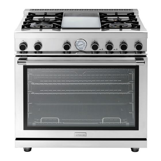
Summary of Contents for Techogas Superiore RN362GPSS
- Page 1 INSTALLATION MANUAL FOR 30’’ AND 36’’ GAS RANGES...
-
Page 2: Table Of Contents
Table of Contents Warnings & Important Safety Instructions Dimensions Specifications Technical data Clearance Dimensions (Proximity to Cabinets) Clearance Dimensions (Wood/Composite Overlay) Electrical & Gas Requirements General Information Installation/ Door Removal Leg Installation/Adjustments/Alignments Anit-tip Device Installation Connecting Gas & Electrical Final Preparation Performance Checklist Service &... -
Page 3: Warnings & Important Safety Instructions
Warnings & Important Safety Instructions Your safety and the safety of others • Before beginning, please read these instructions completely and carefully. is very important. • DO NOT remove permanently affixed labels, warnings, or plates from product. We have provided many important safety This may void the warranty. - Page 4 Warnings & Important Safety Instructions A GFI shall be used if required by NFPA-70 (National Electric Code), fede- ral/state/local laws, or local ordinances. •The required use of a GFI is normally related to the location of a receptacle with respect to any significant sources of water or moisture. •TECNOGAS SUPERIORE will NOT warranty any problems resulting from GFI out- lets which are not installed properly or do not meet the requirements below.
- Page 5 Warnings & Important Safety Instructions DANGER WARNING CHEMICAL HAZARD MOVING HAZARD To avoid risk of property To avoid risk of severe damage and/or personal personal injury; this injuryor death; this appliance requires two appliance is not too be or more personnel used as a heating source.
-
Page 6: Dimensions
Dimensions 30” Gas Ranges Note: Unit shown with island trim. Note: All gas ranges are equipped with spacer on the back ( 25/64 ) to prevent over heating of the wall. - Page 7 Dimensions 30” Gas Ranges 29" 7 /8 29" 7 /8 3 /8 1" Electricity 2" 5" 9 /16 2" 26" 7 /8 11 /32 1" 3 /8 2" 3 /8 " 2" 27 /64 1 /2 1" 3 /16 11 /32 2"...
- Page 8 Dimensions 36”Gas Ranges Note: Unit shown with island trim. Note: All gas ranges are equipped with spacer on the back ( 25/64 ) to prevent over heating of the wall.
- Page 9 Dimensions 36”Gas Ranges 35" 7 /8 35" 7 /8 3 /8 1" Electricity 2" 5" 9 /16 2" 26" 7 /8 11 /32 1" 3 /8 2" 3 /8 " 2" 27 /64 1 /2 1" 3 /16 11 /32 2"...
-
Page 10: Specifications Technical Data
Specifications Specifications Technical data Burners - injectors and volume, range 30‘‘ (mod..301...) Natural 4’’ LP/Propane 11’’ By-pass Ø Inj. BTU/h Inj. BTU/h BTU/h Small burner 1055 3600 1055 3600 1100 Medium burners 1300 6500 1300 6500 1300 Large burner 2750 11000 2750... -
Page 11: Clearance Dimensions (Proximity To Cabinets)
Clearance Dimensions (Proximity to Cabinets) •This range may be installed directly adjacent to existing 36” (91.4 cm) high base cabinets. IMPORTANT: The side trim MUST be 3/8” (0.95 cm) above the adjacent base cabinet countertop. This can be accomplished by raising the unit adjusting the legs. -
Page 12: Clearance Dimensions (Wood/Composite Overlay)
Clearance Dimensions (Wood/Composite Overlay) The bottom of a standard hood should be 30” (76.2 cm) min. to 36” (91.4 cm) max. above the countertop. This would typically result in the bottom of the hood being 66” (167.6 cm) to 72” (182.9 cm) above the floor. Refer to the range hood installation instructions for additional information. -
Page 13: Electrical & Gas Requirements
Electrical & Gas Requirements Electrical Requirements location where it can be reached quickly Check your national and local codes in the event of an emergency. Any opeing regarding this unit. This range require- behind the range shall be sealed. In Massachusetts: A “T” handle s120VAC/60 Hz;... - Page 14 Gas Requirements TO INSTALL PRESSURE REGULATOR 1: Remove the 2 covers on the back of the 3 - Screw the assembled pressure regu- range unscrewing the 3 screws indicated lator on the range like shown on picture on below pictures. below.
- Page 15 Gas Requirements Flexible Connections: In Canada: CAN 1-6, 10-88 metal If the unit is to be installed with flexible connectors for gas appliances and CAN couplings and/or quick-disconnect fittings, 1-6.9 M79 quick disconnect devices for the installer must use a heavy-duty AGA use with gas fuel.
- Page 16 Gas Requirements GAS CONVERSION STEP1:PRESSURE REGULATOR The pressure regulator supplied with the WARNING! appliance is a convertible type pressure Before carrying out this operation, regulator for use with Natural Gas at a disconnect the appliance from gas and nominal outlet pressure of 4” w.c. or LP electricity.
- Page 17 Gas Requirements STEP 2: SURFACE BURNERS STEP 3: MAIN OVEN BURNER To replace the nozzles of the main oven To replace the nozzles of the surface burner, start by removing the bottom burners, lift up the burners and unscrew panel of the oven. the nozzles shipped with the range using Loose the 2 screw located on the left and a 7 mm (sochet wrench).
- Page 18 Gas Requirements Replace the nozzle using the conversion set STEP 4: BROILER BURNER Loosen the 2 screws on left and right supplied with the range or by a Tecno sides and pull out the burner from its authorized parts warehouse. Each nozzle support burner from its support.
- Page 19 Gas Requirements STEP 5: VISUAL CHECKS STEP 6: MINIMUM Before reinstalling the bottom panel, the FLAME ADJUSTMENT following visual check must be performed WARNING! These adjustments should to ensure that the conversion has been be made only for use of the appliance carried out properly and without damage with natural gas.
- Page 20 Gas Requirements OVEN BURNER 1. Set the oven temperature control knob to the MAXIMUM setting. 2. Close the oven door and operate the oven for at least 10 minutes. 3. Set the knob to the MINIMUM setting 4. Remove the knob. 5.
-
Page 21: General Information
General Information Moving, Handling and Unpacking READ AND FOLLOW ALL WARNING AND CAUTION Remove and discard all packing materials, including cardboard and tape INFORMATION WHEN INSTAL- LING THIS APPLIANCE. on the outside and inside of the range. Remove the burner grates and styrofoam off the top cooking surface. -
Page 22: Installation/Door Removal
Installation/Door removal NOTICE DO NOT use the handle or oven door to lift the oven. DO NOT lift or carry the door by the handle. Removing the door must be done by your dealer, a qualified licensed plumber, or certified gas installer Door Removal 1)- Open the door completely. -
Page 23: Leg Installation/Adjustments/Alignments
Leg Installation/Adjustments/Alignment Adjust leg height to the desired level by Tecnogas ranges must be used only with twisting the inside portion of the leg as- the legs properly installed. sembly until the proper height is reached. Check with a level that the worktop allignement is perfectly level. -
Page 24: Anit-Tip Device Installation
Anti-tip Device Installation WARNING TIPPING HAZARD: To reduce the risk of property damage or personal injury; install anti-tipping device provided in accordance with the installation instructions in this document. Device must be engaged properly to prevent product from tipping over. TIPPING Wall Range side panel... -
Page 25: Connecting Gas & Electrical
Connecting Gas & Electric DANGER GAS LEAK HAZARD To avoid risk of personal injury or death; leak testing of the appliance must be conducted according to the manufacturer’s instructions. Before placing appliance in operation, always check for gas leaks with soapy water solution. •... -
Page 26: Final Preparation
Final Preparation •All stainless steel body parts should be soak wiped with hot, soapy water and with a with hot, wet cloths to loosen the ma- liquid cleaner designed for this material. terial, then use a wool or nylon scraper. If buildup occurs, DO NOT use steel DO NOT use a metal knife, spatula, or wool, abrasive cloths, cleansers, or pow-... - Page 27 Performance Checklist Worktop burner knob + simmer = Closed position = “Full on” position internal ring = “Full on” position esternal ring Gas oven switch knob range 30’’ = Closed position from MIN = Oven temperatures to MAX (300-450 °F) Broil = Broil Gas oven switch knob range 36’’...
-
Page 28: Service & Registration
Service & Registration Only authorized replacement parts may be used in performing service on the appliance. All servicing should be referred to a qualified technician. Contact TECNOGAS SUPERIORE 1-844-322-2111, for the nearest service parts distributor in your area or write to: CUSTOMERCARE@TECNOSPA.IT Record the information indicated below. -
Page 29: Warranty Usa
WARRANTY U.S.A Please record your model (MOD) and serial number (S/N) below for future reference. For your convenience, a label containing this information is supplied with this booklet. When writing or calling about a service problem, please include the following information: - your name, address and telephone number - appliance model and serial number - name and address of your dealer... - Page 30 WARRANTY U.S.A 6) Any repair, modification, alteration, or adjustment provided by any person not authorized by TECNOGAS SUPERIORE. 7) Failure of the product if it is abused, misused or used for other than the intended purpose or if used commercially/industrially. 8) Incorrect electric current, voltage or power supply.
- Page 31 Electric diagram 30”...
- Page 32 Electric diagram 36” 6 burners...
- Page 33 Electric diagram 36”4 burners + griddle...
- Page 34 Labels...
- Page 36 tecnogassuperiore.us...
Need help?
Do you have a question about the Superiore RN362GPSS and is the answer not in the manual?
Questions and answers