Table of Contents
Advertisement
Quick Links
Advertisement
Table of Contents

Related Manuals for Techogas RN483GXSS


Summary of Contents for Techogas RN483GXSS
- Page 1 INSTALLATION MANUAL FOR 48’’ GAS RANGES...
-
Page 2: Table Of Contents
Table of Contents Warnings & Important Safety Instructions Dimensions Specifications Technical data Clearance Dimensions (Proximity to Cabinets) Clearance Dimensions (Wood/Composite Overlay) Electrical & Gas Requirements General Information Installation/ Door Removal Leg Installation/Adjustments/Alignments Anit-tip Device Installation Connecting Gas & Electrical Final Preparation Performance Checklist Service &... -
Page 3: Warnings & Important Safety Instructions
Warnings & Important Safety Instructions Your safety and the safety of others • Before beginning, please read these instructions completely and carefully. is very important. • DO NOT remove permanently affixed labels, warnings, or plates from product. We have provided many important safety This may void the warranty. - Page 4 Warnings & Important Safety Instructions A GFI shall be used if required by NFPA-70 (National Electric Code), fede- ral/state/local laws, or local ordinances. •The required use of a GFI is normally related to the location of a receptacle with respect to any significant sources of water or moisture. •TECNOGAS SUPERIORE will NOT warranty any problems resulting from GFI out- lets which are not installed properly or do not meet the requirements below.
- Page 5 Warnings & Important Safety Instructions DANGER WARNING CHEMICAL HAZARD MOVING HAZARD To avoid risk of property To avoid risk of severe damage and/or personal personal injury; this injuryor death; this appliance requires two appliance is not too be or more personnel used as a heating source.
-
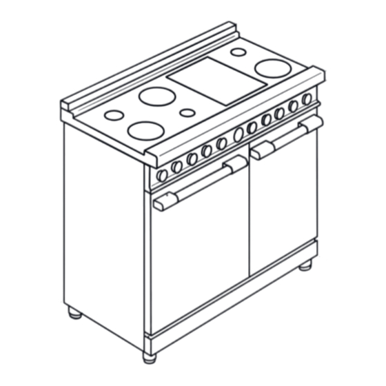
Page 6: Dimensions
Dimensions 48” Gas Ranges Note: Unit shown with island trim. Note: All gas ranges are equipped with spacer on the back ( 25/64 ) to prevent over heating of the wall. - Page 7 Dimensions 48” Gas Ranges 47" 7 /8 47" 7 /8 3 /8 1" Electricity 2" 5" 9 /16 2" 26" 7 /8 11 /32 1" 3 /8 2" 3 /8 " 2" 27 /64 1 /2 1" 3 /16 11 /32 2"...
- Page 8 Specifications Specifications Technical data Burners - injectors and volume Range Mod..482... Methane 4’’ LPG 10’’ By-pass Burners Inj. BTU/h Inj. BTU/h Ø BTU/h Small burner 1055 3600 1055 3600 1100 Medium burner 1661 6500 1661 6500 1300 Large burner 2931 11000 2931...
-
Page 9: Specifications Technical Data
Specifications Technical data Induction and Burners - injectors and volume Range Mod..483... Methane 4’’ LPG 10’’ By-pass Burners Ø Inj. BTU/h Inj. BTU/h BTU/h Medium burner 1661 6500 1661 5700 1300 Ext. 137 (2) 82 (2) ring Power burner 5275 18000 5275... -
Page 10: Clearance Dimensions (Proximity To Cabinets)
Clearance Dimensions (Proximity to Cabinets) This range may be installed • directly adjacent to existing 36″ (91.4 cm) high base cabinets. IMPORTANT: The side trim MUST be 3/8” (0.95 cm) above the adjacent base cabinet countertop. This can be accomplished by raising the unit adjusting the legs. -
Page 11: Clearance Dimensions (Wood/Composite Overlay)
Clearance Dimensions (Wood/Composite Overlay) The bottom of a standard hood should be 30 ‘‘ (76.2 cm) min to 36 ‘‘ (91.4 cm) max to above the countertop. This would typically result in the bottom of the hood being 66” (167.6 cm) to 72” (182.9 cm) above the floor. Refer to the range hood installa- tion instructions for additional information. -
Page 12: Electrical & Gas Requirements
Electrical & Gas Requirements Electrical Requirements Manual shut-off valve: Check your national and local codes This installer-supplied valve must be regarding this unit. The ranges series installed in the gas service line before RN482... and RD482... require120VAC/60 the appliance in the gas stream and in a Hz;... -
Page 13: Gas Requirements
Gas Requirements TO INSTALL PRESSURE REGULATOR 1: Remove the 2 covers on the back of the 3 - Screw the assembled pressure regu- range unscrewing the 3 screws indicated lator on the range like shown on picture on below pictures. below. - Page 14 Gas Requirements Flexible Connections: In Canada: CAN 1-6, 10-88 metal If the unit is to be installed with flexible connectors for gas appliances and CAN couplings and/or quick-disconnect fittings, 1-6.9 M79 quick disconnect devices for the installer must use a heavy-duty AGA use with gas fuel.
-
Page 15: Gas Conversion
Gas Requirements GAS CONVERSION STEP1:PRESSURE REGULATOR The pressure regulator supplied with the WARNING! appliance is a convertible type pressure Before carrying out this operation, regulator for use with Natural Gas at a disconnect the appliance from gas and nominal outlet pressure of 4” w.c. or LP electricity. - Page 16 Gas Requirements STEP 2: SURFACE BURNERS STEP 3: MAIN OVEN BURNER To replace the nozzles of the main oven To replace the nozzles of the surface burner, start by removing the bottom burners, lift up the burners and unscrew panel of the oven. the nozzles shipped with the range using Loose the 2 screws located on the left and a 7 mm (sochet wrench).
- Page 17 Gas Requirements STEP 5: BROILER BURNER (auxi- STEP 4: BROILER BURNER (MAIN) Loosen the 2 screws on left and right liary) sides and pull out the burner from its To replace the noozle of the small oven support burner from its support. burner start by removing the bottom ATTENTION: pay extra attention panel...
-
Page 18: Flame Adjustment
Gas Requirements STEP 6: VISUAL CHECKS STEP 7: MINIMUM Before reinstalling the bottom panel, the FLAME ADJUSTMENT following visual check must be performed WARNING! These adjustments should to ensure that the conversion has been be made only for use of the appliance carried out properly and without damage with natural gas. -
Page 19: General Information
General Information Remove the burner grates and READ AND FOLLOW ALL styrofoam off the top cooking surface. Be WARNING AND CAUTION sure to remove the burner caps packaged INFORMATION WHEN INSTAL- in styrofoam below the burner grates. LING THIS APPLIANCE. Do not discard the anti-tip •... -
Page 20: Installation/Door Removal
Installation/Door removal NOTICE DO NOT use the handle or oven door to lift the oven. DO NOT lift or carry the door by the handle. Removing the door must be done by your dealer, a qualified licensed plumber, or certified gas installer Door Removal 1)- Open the door completely. -
Page 21: Leg Installation/Adjustments/Alignments
Leg Installation/Adjustments/Alignment Tecnogas ranges must be used only with the legs properly installed. Six height adjustable legs are delivered with the range in the polysterene container situated over the appliance. Before installing the legs, position the appliance near its final location as the legs are not suitable for moving the appliance over long distances. - Page 22 Anti-tip Device Installation HAZARD: To reduce the risk of property damage or personal injury; install anti-tipping device provided in accordance with the installa- tion instructions in this document. Device must be engaged properly to pre- vent product from tipping over. Kit enclosed with the range.
- Page 23 Connecting Gas & Electric DANGER GAS LEAK HAZARD To avoid risk of personal injury or death; leak testing of the appliance must be conducted according to the manufacturer’s instructions. Before placing appliance in operation, always check for gas leaks with soapy water solution. •...
-
Page 24: Final Preparation
Final Preparation •All stainless steel body parts should be soak with hot, wet cloths to loosen the wiped with hot, soapy water and with a material, then use a wool or nylon scra- per. DO NOT use a metal knife, spatula, liquid cleaner designed for this material. - Page 25 Performance Checklist Rotary switch knob = Closed position = Oven light on = Oven light on - fan = Fan LEFT CAVITY Gas oven switch knob range 48’’ = Closed position from MIN = Oven temperatures to MAX (300-450 °F) Broil = Broil RIGHT CAVITY...
- Page 26 Performance Checklist Induction zone knob Cooking zone Off (not activated) = Accelerated heat-up = Turbo Boost/Bridge from 1-9 = Induction power levels = Induction special functions: Melting, Warming, Simmering...
-
Page 27: Service & Registration
Service & Registration Only authorized replacement parts may be used in performing service on the appliance. All servicing should be referred to a qualified technician. Contact TECNOGAS SUPERIORE 1-844-322-2111, for the nearest service parts distributor in your area or write to: CUSTOMERCARE@TECNOSPA.IT Record the information indicated below. -
Page 28: Warranty Usa
WARRANTY U.S.A Please record your model (MOD) and serial number (S/N) below for future reference. For your convenience, a label containing this information is supplied with this booklet. When writing or calling about a service problem, please include the following information: - your name, address and telephone number - appliance model and serial number - name and address of your dealer... - Page 29 WARRANTY U.S.A 6) Any repair, modification, alteration, or adjustment provided by any person not authorized by TECNOGAS SUPERIORE. 7) Failure of the product if it is abused, misused or used for other than the intended purpose or if used commercially/industrially. 8) Incorrect electric current, voltage or power supply.
- Page 30 Labels...
- Page 32 tecnogassuperiore.us...
Need help?
Do you have a question about the RN483GXSS and is the answer not in the manual?
Questions and answers