Table of Contents
Advertisement
Quick Links
User's and Service Guide
Agilent Technologies 85052D
3.5 mm Economy Calibration Kit
This manual directly applies to 85052D calibration kits with serial number prefix
3106A.
Agilent Part Number: 85052-90079
Printed in USA
Print Date: November 2004
Supersedes: March 2004
© Copyright 1994–1995, 2000–2002, 2004 Agilent Technologies, Inc. All rights reserved.
Advertisement
Table of Contents
Troubleshooting

Related Manuals for Agilent Technologies 85052D


Summary of Contents for Agilent Technologies 85052D
- Page 1 User’s and Service Guide Agilent Technologies 85052D 3.5 mm Economy Calibration Kit This manual directly applies to 85052D calibration kits with serial number prefix 3106A. Agilent Part Number: 85052-90079 Printed in USA Print Date: November 2004 Supersedes: March 2004 © Copyright 1994–1995, 2000–2002, 2004 Agilent Technologies, Inc. All rights reserved.
- Page 2 2.101(a) or as “Restricted computer software” as defined in FAR 52.227-19 (June 1987) or any equivalent agency regulation or contract clause. Use, duplication or disclosure of Software is subject to Agilent Technologies’ standard commercial license terms, and non-DOD Departments and Agencies of the U.S. Government will receive no greater than Restricted Rights as defined in FAR 52.227-19(c)(1-2) (June 1987).
- Page 3 Printing Copies of Documentation from the Web To print copies of documentation from the Web, download the PDF file from the Agilent web site: • Go to http://www.agilent.com. • Enter the document’s part number (located on the title page) in the Quick Search box. •...
-
Page 5: Table Of Contents
85052D Kits with Serial Prefix 3027A........ - Page 6 Blank Form ............. .A-12 Contents-vi 85052D...
-
Page 7: General Information
General Information 85052D... -
Page 8: Calibration Kit Overview
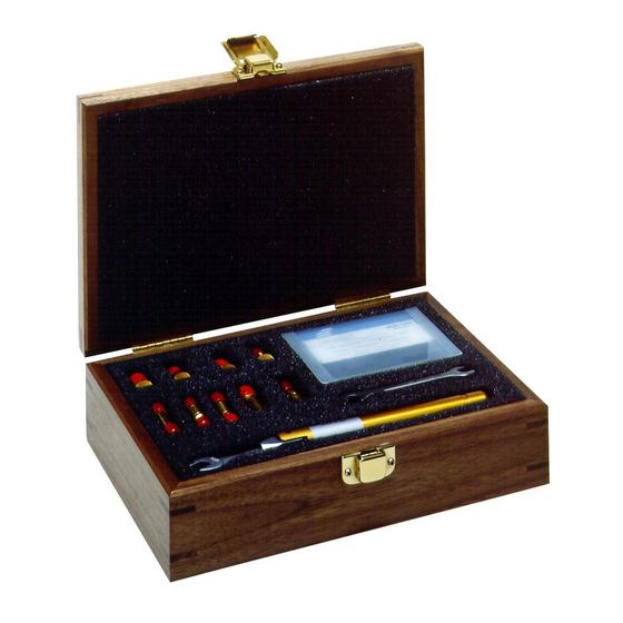
General Information Calibration Kit Overview Calibration Kit Overview The Agilent 85052D 3.5 mm calibration kit is used to calibrate Agilent network analyzers up to 26.5 GHz for measurements of components with 3.5-mm connectors. Kit Contents The 85052D calibration kit includes the following items: •... -
Page 9: Calibration Definitions
Equipment Required but Not Supplied Some items are required or recommended for successful operation of your kit, but are not supplied with the kit. Refer to Table 6-2 on page 6-3 for a list of these items and for ordering information. 85052D... -
Page 10: Incoming Inspection
. Recording the serial numbers will prevent confusing the devices in this kit with similar devices from other kits. The adapters included in the kit are for measurement convenience only and are not serialized. Table 1-1 Serial Number Record for the 85052D Device Serial Number Calibration kit _______________________________ Broadband load –m–... -
Page 11: Calibration Kits Documented In This Manual
This section describes calibration kits with serial number prefixes lower that the ones listed on the title page. 85052D Kits with Serial Prefix 3027A These calibration kits did not have the calibration constants disk to support the Agilent 8510C network analyzer. The part numbers provided in this manual are the recommended replacement parts for these kits. - Page 12 Improper connections, resulting from pin depth values being out of the observed limits (see Table 2-2 on page 2-4) or from bad connection techniques, can also damage these devices. 85052D...
-
Page 13: Specifications
Specifications 85052D... -
Page 14: Environmental Requirements
During a measurement calibration, the temperature of the calibration devices must be stable and within the range shown in Table 2-1. Avoid unnecessary handling of the devices during calibration because your IMPORTANT fingers are a heat source. 85052D... -
Page 15: Mechanical Characteristics
Mechanical characteristics such as center conductor protrusion and pin depth are not performance specifications. They are, however, important supplemental characteristics related to electrical performance. Agilent Technologies verifies the mechanical characteristics of the devices in the kit with special gaging processes and electrical testing. - Page 16 Approximately +2 sigma to −2 sigma of gage uncertainty based on studies done at the factory according to recommended procedures. b. Observed pin depth limits are the range of observation limits seen on the gage reading due to measurement uncertainty. The depth could still be within specifications. 85052D...
-
Page 17: Electrical Specifications
The electrical specifications in Table 2-3 apply to the devices in your calibration kit when connected with an Agilent precision interface. Table 2-3 Electrical Specifications for 85052D 3.5 mm Devices Device Specification Frequency (GHz) Return loss ≥ 46 dΒ (ρ ≤ 0.00501) dc to ≤... -
Page 18: Residual Errors After Calibration
Certification Agilent Technologies certifies that this product met its published specifications at the time of shipment from the factory. Agilent further certifies that its calibration measurements are traceable to the United States National Institute of Standards and Technology (NIST) to the extent allowed by the institute’s calibration facility, and to the calibration facilities... -
Page 19: Use, Maintenance, And Care Of The Devices
Use, Maintenance, and Care of the Devices 85052D... -
Page 20: Electrostatic Discharge
4. Remove the short from the cable. Figure 3-1 shows a typical ESD protection setup using a grounded mat and wrist strap. Refer to Table 6-2 on page 6-3 for information on ordering supplies for ESD protection. Figure 3-1 ESD Protection Setup 85052D... -
Page 21: Visual Inspection
If a connector shows deep scratches or dents, particles clinging to the mating plane surfaces, or uneven wear, clean and inspect it again. Devices with damaged connectors should be discarded. Determine the cause of damage before connecting a new, undamaged connector in the same configuration. 85052D... -
Page 22: Inspect Female Connectors
414 kPa (60 psi) to control the velocity of the air stream. High-velocity streams of compressed air can cause electrostatic effects when directed into a connector. These electrostatic effects can damage the device. Refer to “Electrostatic Discharge” earlier in this chapter for additional information. 85052D... - Page 23 Let the alcohol evaporate, then blow the connector dry with a gentle stream of clean, low-pressure compressed air or nitrogen. Always completely dry a connector before you reassemble or use it. 4. Inspect Inspect the connector to make sure that no particles or residue remain. Refer to “Visual Inspection” on page 3-3. 85052D...
-
Page 24: Gaging Connectors
Use, Maintenance, and Care of the Devices Gaging Connectors Gaging Connectors The gages available from Agilent Technologies are intended for preventive maintenance and troubleshooting purposes only. They are effective in detecting excessive center conductor protrusion or recession, and conductor damage on DUTs, test accessories, and the calibration kit devices. -
Page 25: When To Gage Connectors
(due to wear or damage, for example). • If a calibration device is used by someone else or on another system or piece of equipment. • Initially, after every 100 connections, and after that, as often as experience indicates. 85052D... -
Page 26: Gaging Procedures
After each measurement, rotate the gage a quarter-turn to reduce measurement variations that result from the gage or the connector face not being exactly perpendicular to the center axis. e. Compare the average reading with the observed pin depth limits in Table 2-2 on page 2-4. 85052D... - Page 27 Use, Maintenance, and Care of the Devices Gaging Connectors Figure 3-2 Gaging 3.5 mm Connectors 85052D...
-
Page 28: Connections
Refer to Table 6-1 on page 6-2 for replacement part number and ordering information. Table 3-1 Torque Wrench Information Connector Type Torque Setting Torque Tolerance ±9.0 N-cm (±0.8 in-lb) 3.5 mm 90 N-cm (8 in-lb) 3-10 85052D... - Page 29 3. Apply downward force perpendicular to the wrench handle. This applies torque to the connection through the wrench. Do not hold the wrench so tightly that you push the handle straight down along its length rather than pivoting it; otherwise, you apply an unknown amount of torque. 85052D 3-11...
-
Page 30: How To Separate A Connection
• Do not set connectors contact-end down on a hard surface. The plating and the mating plane surfaces can be damaged if the interface comes in contact with any hard surface. 3-12 85052D... -
Page 31: Performance Verification
Performance Verification 85052D... -
Page 32: Introduction
These two steps establish a traceable link to NIST for Agilent to the extent allowed by the institute’s calibration facility. The specifications data provided for the devices in the kit is traceable to NIST through Agilent Technologies. 85052D... -
Page 33: Recertification
A list of NIST traceable numbers may be purchased upon request to be included in the calibration report. Agilent Technologies offers a Standard calibration for the recertification of the kit. For more information, contact Agilent Technologies. Refer to “Contacting Agilent” on page 5-4 for a list of offices. - Page 34 Performance Verification Recertification 85052D...
-
Page 35: Troubleshooting
Troubleshooting 85052D... -
Page 36: Troubleshooting Process
Troubleshooting Troubleshooting Process Troubleshooting Process If you suspect a bad calibration, or if your network analyzer does not pass performance verification, follow the steps in Figure 5-1. Figure 5-1 Troubleshooting Flowchart 85052D... -
Page 37: Returning A Kit Or Device To Agilent
Troubleshooting Returning a Kit or Device to Agilent Returning a Kit or Device to Agilent If your kit or device requires service, contact Agilent Technologies for information on where to send it. See “Contacting Agilent” on page 5-4 for contact information. Include a... -
Page 38: Contacting Agilent
(tel) (+44) (0)7004 666666 (alt) (+39) (0)2 9260 8484 (alt) (+44) (0)7004 123123 (fax) (+41) (0)22 567 5314 (fax) (+44) (0)7004 444555 (tel) = primary telephone number; (alt) = alternate telephone number; (fax) = FAX number; * = in country number 8/03/04 85052D... -
Page 39: Replaceable Parts
Replaceable Parts 85052D... -
Page 40: Introduction
Replaceable Parts Introduction Introduction Table 6-1 lists the replacement part numbers for the 85052D calibration kit. Table 6-2 lists the replacement part numbers for items not included in the calibration kit that are either required or recommended for successful operation of the kit. - Page 41 Replaceable Parts Introduction Table 6-1 Replaceable Parts for the 85052D Calibration Kit Description Qty per Agilent Part Number Disk holder 5180-8491 Miscellaneous Items Calibration constants disk (8510, 872x series) 85052-10012 Calibration constants disk (PNA series) 85052-10017 08510-10033 Specifications and performance verification disk User’s and service guide...
- Page 42 Replaceable Parts Introduction Figure 6-1 Replaceable Parts for the 85052D Calibration Kit 85052D...
- Page 43 Replaceable Parts Introduction Figure 6-2 Replaceable Parts for the 85052D Calibration Kit 85052D...
- Page 44 Replaceable Parts Introduction 85052D...
-
Page 45: A Standard Definitions
Standard Definitions 85052D... -
Page 46: Standard Class Assignments
Adapter TRL Option Cal Z : _____ System Z __X__ Line Z Set ref: __X__ Thru _____ Reflect Lowband frequency: ________ a. The forward isolation standard is also used for the isolation part of the response and isolation calibration. 85052D... - Page 47 Reverse match Thru Response Response Response & isolation Response TRL thru Thru TRL reflect Open TRL line or match Loads TRL Option Cal Z : _____ System Z __X__ Line Z Set ref: __X__ Thru _____ Reflect Lowband frequency: ______ 85052D...
- Page 48 Standard Definitions Standard Class Assignments Table A-3 Standard Class Assignments for the PNA Series Network Analyzer Calibration Kit Label: 3.5 mm 85052D Class Notes: 1. If you are performing a TRL calibration: • S T and S T must be defined as thru standards.
-
Page 49: Blank Forms
_____ Line Z Set ref: _____ Thru _____ Reflect Lowband frequency ___________ a. The forward isolation standard is also used for the isolation part of the response and isolation calibration. b. Broadband loads are used for frequencies up to 2 GHz. 85052D... - Page 50 Response & isolation TRL thru TRL reflect TRL line or match TRL Option Cal Z _____ System Z _____ Line Z Set ref: _____ Thru _____ Reflect Lowband frequency ___________ a. Broadband loads are used for frequencies up to 2 GHz. 85052D...
- Page 51 C must be defined as the same standard. 5. S B and S C must be defined as the same standard. For additional information on performing TRL, TRM, and LRM calibrations, refer to your PNA series network analyzers embedded help system. 85052D...
-
Page 52: Nominal Standard Definitions
Class assignments and standard definitions may change as more accurate model and calibration methods are developed. The disk shipped with the kit for use with the 8510 will contain the most recent version. The default version that comes with the 872x network analyzer firmware may be outdated. 85052D... - Page 53 Load or arbitrary impedance only. d. For waveguide, the lower frequency is the same as F e. Typical values only. Disk values may be different. f. This standard type (open) is used to accurately model the adapter listed in the Standard Label column. 85052D...
- Page 54 Thru thru Ensure system Z of network analyzer is set to this value. b. Open, short, load, delay/thru, or arbitrary impedance. c. Load or arbitrary impedance only. d. For waveguide, the lower frequency is the same as F A-10 85052D...
- Page 55 Standard Definitions Nominal Standard Definitions Table A-9 Standard Definitions for the PNA Series Network Analyzer = 50.0 Ω Calibration Kit Label: 3.5 mm Model 85052D System Z Frequency Offset Standard in GHz −108.54 −0.01 Short 2.0765 2.1705 31.785 50 2.366...
-
Page 56: Blank Form
GHz a. Ensure system Z of network analyzer is set to this value. b. Open, short, load, delay/thru, or arbitrary impedance. c. Load or arbitrary impedance only. d. For waveguide, the lower frequency is the same as F A-12 85052D... - Page 57 GHz Ensure system Z of network analyzer is set to this value. b. Open, short, load, delay/thru, or arbitrary impedance. c. Load or arbitrary impedance only. d. For waveguide, the lower frequency is the same as F 85052D A-13...
- Page 58 GHz Short Open Broadband Load Thru a. Ensure system Z of network analyzer is set to this value. b. Open, short, load, delay/thru, or arbitrary impedance. c. For waveguide, the lower frequency is the same as F A-14 85052D...
- Page 59 Agilent Technologies compressed air entering contacting for cleaning permanently stored alcohol conductive mat, part number standard isopropyl deviation from nominal as cleaning solvent...
- Page 60 3-12 Index-ii 85052D...
- Page 61 A-12 user’s and service guide blank forms A-12 part number nominal standards international National Institute of Standards and Technology (NIST) verification performance static temperature discharge visual inspection electricity storage 3-12 storage case, part number 85052D Index-iii...
- Page 62 Index Index-iv 85052D...