
Subscribe to Our Youtube Channel
Related Manuals for Guilin Woodpecker Medical Instrument Ai-Motor MotoPex


Summary of Contents for Guilin Woodpecker Medical Instrument Ai-Motor MotoPex
- Page 1 Please read this User Manual carefully before use for operating instructions, care and maintenance.
-
Page 2: Table Of Contents
Contents 1 Product introduction ................1 2 Installation ..................... 6 3 Function and operation of product ............14 4 Operation instruction ................17 5 Troubleshooting ................... 31 6 Cleaning, Disinfection and Sterilization ..........32 7 Storage, maintenance and transportation ..........41 8 Environmental protection .............. -
Page 3: Product Introduction
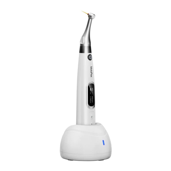
Curing light, Apex locators, Ultrasurgery equipment, Endo Motors, etc. 1.2 Product description Endo Motor ( model: Ai-Motor MotoPex) is used in Endodontic treatment. It is a cordless endo motor with an integrated apex locator. It can be used as an endo motor to prepare and enlarge root canals or as a device for measuring canal length. - Page 6 1.5 Scope of application 1.5.1 The device can be used for preparation and enlargement of root canals, or device for measuring canal length. 1.5.2 This device must only be used in hospital environments, clinics or dental offices by qualified dental personnel 1.6 Contraindication This endo motor with an integrated apex locator should be used with caution in patients with a cardiac pacemaker.
- Page 7 1.7.10 Do not activate the push button on the contra-angle head during operation or slow down This leads to damage of the head or instrument separation. 1.7.11 Do not remove the contra-angle head when the handpiece is rotating. If removed may result in the damage of the gear inside the motor handpiece 1.7.12 Please confirm whether the file is well inserted and locked before starting the motor handpiece.
-
Page 8: Installation
1.9 Primary technical specifications 1.9.1 Battery Lithium battery in motor handpiece: 3.7V /2000mAh 1.9.2 Power adapter (Model: DJ-0500100-A5) Input: ~100V-240V 50Hz/60Hz 0.5-0.2A Output: DC5V/1A 1.9.3 Torque rang: 0.4Ncm-5.0Ncm ( 4mNm ~ 50mNm ) 1.9.4 Speed rang: 100rpm~1200rpm 1.9.5 Wireless charging (only for Ai-Motor) Frequency range: 112-205KHz Maximum RF output power of the product: 9.46dBuA/m@3m 1.10 Environment parameters... - Page 9 Power adapter Measuring wire File clip Lip hook Touch probe Disposable insulation sleeves Display Screens 2.2.1 Display Screens for 5 Operation Modes and Standby 2.2.1.1 EAL Mode This mode is for canal measurement. The motor handpiece does not run in this mode . 2.2.1.2 CW Mode The motor handpiece rotates forward 360º, clockwise direction.
- Page 10 2.2.1.3 CCW Mode The motor handpiece rotates in a counterclockwise direction only. This mode is used to inject calcium hydroxide or any other intracanal medicament. When this mode is used, a double-beep sound will be heard continuously. 2.2.1.4 REC Mode Reciprocating mode.
- Page 11 When the load on the file is greater than the set torque limit, the file will start to rotate alternately at the set angle. 2.2.2 Torque Display This appears when the device is operating. Display shows the torque load on the file.
- Page 12 2.2.3 Canal Measurement Display This appears when a file is inside the canal and the lip hook is in contact with the patient’s lip. Bars on the display show the location of the file tip in the root canal. In the EAL Mode, If the length is less than 1.0, the display will be enlarged.
- Page 13 2.4 Installation and removal of contra angle. 2.4.1 Installation Align one of the locating pins of the contra-angle with the positioning slot on the motor handpiece and push the contra-angle horizontally. When the three locating pins on the contra-angle are inserted into the corresponding three positioning holes on the motor handpiece a “click”...
- Page 14 Warnings: a) Before plugging in or pulling out contra angle head, please make sure the device is not in function. Please ensure Contra angle is inserted properly into the hand piece before use. 2.5 Insertion and removal of file 2.5.1 Insertion of file The file should be inserted into the contra- angle head before starting the hand Press the push button on the contra-angle and insert the file.
- Page 15 Warnings: Before Inserting and removing the file, the motor handpiece should not be in function. Be careful when removing files to prevent injury to fingers. Removing files without pressing the push button will damage the chuck of the contra-angle. 2.6 Working length measurement Assembly Working Length Measurement Connection.
- Page 16 Warnings: Connect the lip hook to the socket (white) on the measurement cable io monitor working length during the root canal preparation Installation and removal of disposable insulation sleeves 2.7.1 Installation Before each use of the handpiece and after the handpiece is cleaned and disinfected, a disposable isolation sleeve should be used to cover the handpiece.
- Page 17 Refer to Chapter 6.3 for cleaning and disinfection procedures. 2.7.2 Removing After each use, remove the barrier film and slowly pull the isolation sleeve from the thin end of the handpiece. Warming: Isolation sleeves are not reusable.
-
Page 18: Function And Operation Of Product
3 Function and operation of product 3.1 Button definition and settings Power on Press the Main button to turn on the motor handpiece. Power off Hold down the Setting button “P”, then press the Main button to turn off motor handpiece. Customized program change Press Adjusting button “+”/ “-”... - Page 19 and press Main button to entry handpiece functions setting, press Setting button “P” till target setting, press Adjusting button “+”/“-” to adjust, then press the Main button to confirm. 3.2 Screen display Standby interface a. Customized program sequence number 0-9, total 10 programs. b.
- Page 20 Apical reference point setting interface a. Apical reference point flash bar b. Apical foramen c. Digital “02” meter reading, very close to the apical foramen. 3.3 Terms and definition Clockwise rotation, forward ration applicable to rotary file Counterclockwise rotation, reverse rotation applicable to special files / lentilospirals to inject calcium hydroxide or any other intracanal medicaments or root canal sealers...
-
Page 21: Operation Instruction
The file slows down automatically as it Apical Slow Down approaches the apex. Activating in CW and CCW operation mode. 5 operation modes for canal shaping and Operation Mode measurement. Such as CW, CCW, REC, ATR and EAL. Speed File rotation speed. For CW and CCW modes, the torque value Torque (Torque Limit) that triggers reverse rotation. - Page 22 base. 4.2 Selecting customized program sequence number The motor handpiece has 10 memory programs(M0-M9) and 5 preset programs, press the adjusting button “+”/“-” to change the customized program sequence number during the standby state. M0-M9 is a memory program for canal shaping and measurement, every memory program has its own parameters such as Operation mode, speed and torque, all these parameters can be changed if required.
- Page 23 The speed setting can be adjusted from 100 rpm to1200 rpm. Press the Adjusting button “+”/“-” to increase or decrease the speed. Press the button for a long time to increase or decrease the speed. In ATR mode, speeds of 100~500rpm are available.
- Page 24 The file starts rotating automatically as soon as the file is inserted into the canal and the canal length indicator bar lights up more than 2 bars. Press the Adjusting button “+”/“-” to change. OFF: The file does not start rotating on inserting the file into the canal.
- Page 25 Only activating in REC and ATR operation mode. F: Forward Angle. In the REC mode, the Forward Angle of 20°~400° is available. In the ATR mode, the Forward Angle of 60°~400° is available. R: Reverse Angle In the REC mode, the Reverse Angle of 20°~400°...
- Page 26 After selecting the file system, press the Setting button “P” to enter the select file number, press the adjusting button “+”/“-” to select the file number. Press the main button to confirm. The parameters of "W3-Pro" can also be changed from the default setting. To return to the default setting, press the Setting button “P”...
- Page 27 Press the Setting button “P” again, the “Auto Standby Scr” can be changed, press Adjusting button “+”/“-” to adjust the time , and then press "Main" button to confirm. If no buttons are pressed, auto return to standby display of the motor handpiece can be set from 3to 30 seconds in 1 second increments.
- Page 28 4.6 Protective function of automatic reverse During operation, if the load value exceeds the preset torque value, the file rotation mode will automatically change to Reverse Mode. The file would return to normal rotation mode once the load is below the preset torque value again.
- Page 29 Cautions: 1. Protective function of automatic reverse is ONLY suitable for CW mode. 2. In REC mode, when the load value is higher than the preset torque value if the Forward angle is greater than the Reverse angle, the file rotation automatically changes to reverse rotation, and if the Forward angle is less than the Reverse angle, the file rotation automatically changes to forward rotation.
- Page 30 Motor combined canal measurement function mode When using the motor combined with the integrated apex locator function, connect the lip hook to the socket (white) on the measurement cable to monitor working length during the root canal preparation, keep the black socket idle.
- Page 31 4.8 Canal measurement operation When using in the apex locator mode. the motor handpiece is suggested to be placed on the charging base to get a better visual angle. Press Setting button “P” once in the standby state, press the adjusting button “+”/“-”...
- Page 32 Connection testing It is strongly recommended to check the connection testing every time before use. Clip the holder onto the lip hook and check that all the bars on the meter on the display light up, If this is not noticed, the measuring wire or file clip should be replaced.
- Page 33 Excessive bleeding into the canal from apical foramen. This bleeding may contact the gingiva and the device shows inaccurate measurement. The bleeding should be arrested before measuring the working length. If Irrigating solutions used in the root canal are in contact with oral tissues, the measurement will be inaccurate.
- Page 34 Re-treatment of a root canal obturated using gutta-percha. The gutta-percha must be completely removed to eliminate its inhibitory effect. After removing the gutta- percha, a small file should be used to establish patency through the apical foramen Place a small amount of saline in the canal and make sure saline does not overflow.
- Page 35 The actual apex for the canal is not the same as that for the radiographic apex. There are cases where the apical foramen is placed coronally compared to the radiographic apex. In these cases, an X-ray might indicate that the file has not reached the apex even though it has actually reached the apical foramen.
-
Page 36: Troubleshooting
It is recommended to contact local distributors or manufacturers to replace the battery. 4.11 Oiling of contra-angle Only the original oil injection nozzle should be used for the oiling of the contra-angle. The contra-angle needs to be lubricated after cleaning and disinfection but before sterilization. -
Page 37: Cleaning, Disinfection And Sterilization
There is a The continuous beep Stop the motor continuous beep sound indicates the handpiece and change sound after starting motor handpiece is in the operating mode to CW Mode. the motor CCW mode. handpiece. Contra angle Calibration failure Clean the contra angle, calibration failure caused due to and recalibrate after oil... - Page 38 6.2 General recommendations . 6.2.1 Use only a disinfecting solution that is approved for its efficacy (VAH/DGHM-listing, CE marking, FDA and Health Canada approval) and in accordance with the DFU of the disinfecting solution manufacturer. 6.2.3 Do not place the contra-angle in a disinfectant solution or in an ultrasonic bath.
- Page 39 2. Wet a soft cloth completely with distilled water or deionized water, to wipe all the surfaces of the components such as handpiece, charger, base, etc. until the surface of the component is free of debris or stains. 3. Wipe the surface of each component with a dry soft nap-free cloth. 4.
- Page 40 Note: a) The cleaning and disinfection must be performed within 10min before use. b) The disinfectant should be sprayed immediately after the use but no foaming is allowed. In addition to 75% alcohol, non-residue disinfectants such as Oxytech from Germany can be used, but the concentration, temperature and time specified by the disinfectant manufacture must be followed.
- Page 41 Remove the products from the base, and rinse away the dirt on the surface of the handpiece with pure water (or distilled water/deionized water); Dry the products with a clean, soft cloth and place them in a clean tray. Notes: a) The water used here must be pure water, distilled water or deionized water.
- Page 42 the contra-angle.
- Page 43 6.4.2 Cleaning The cleaning should be performed no later than 24 hours after the procedure. The cleaning can be divided into automated cleaning and manual cleaning. Automated cleaning is preferred if possible 6.4.2.1 Automated cleaning •The cleaner must be approved by CE certification in accordance with EN ISO 15883.
- Page 44 t o the rinsing connection of the washer-disinfector. Start the program. After the program is finished, remove the product from the washer- disinfector, inspect (refer to the section "Inspection and Maintenance") and the packaging (refer to chapter "Packaging"). Repeat the process if necessary (refer to section "Drying").
- Page 45 6.4.4 Drying If the cleaning and disinfection process does not have an automatic...
- Page 46 drying function, dry it after cleaning and disinfection. Methods: Spread a clean white paper (white cloth) on the flat table, orient the product vertically on the white paper (white cloth), and then dry the product with filtered dry compressed air (maximum pressure 3 bar). No liquid oozing onto the white paper (white cloth), indicates the drying of the product is complete.
- Page 47 6.4.4 Packaging Insert /place the disinfected and dried product and quickly package it in a medical sterilization bag (or special holder, sterile box). Notes: a) The package used should conform to ISO 11607 standards b) The packing should withstand high temperature of 138 °C and has sufficient steam permeability.
-
Page 48: Storage, Maintenance And Transportation
c) Do not use hot air sterilization and radiation sterilization as this may result in damage to the product. d) Please use the recommended sterilization procedures for sterilization. It is not recommended to sterilize with sterilization procedures such as ethylene oxide, formaldehyde and low temperature plasma sterilization. -
Page 49: Environmental Protection
7.1.1 Avoid storage in too cold conditions. when the temperature of the equipment increases to a normal level, there will be dew that will possibly damage the PCB board. Maintenance 7.2.1 This device does not include accessories for repair usage, the repair should be carried out by an authorized person or an authorized after-service center. -
Page 50: Symbol Instruction
11 Symbol instruction Follow Instructions Serial number for Use Date of manufacture Manufacturer Type B applied part Class Ⅱ equipment Ordinary equipment Recovery Used indoor only Keep dry Appliance compliance Handle with care WEEE directive Humidity limitation Temperature limitation Atmospheric CE marked product pressure for storage Authorised Representative in the EUROPEAN... - Page 51 Technical Description Concerning Electromagnetic Emission Table 1: Declaration - electromagnetic emissions Guidance and manufacturer’s declaration - electromagnetic emissions The model Ai-Motor / MotoPex is intended for use in the electromagnetic environment specified below. The customer or the user of the model Ai-Motor 、 MotoPex should assure that it is used in such an environment.
- Page 52 Electrical fast ±2kV for power ±2kV for power Mains power quality transient/burst supply lines supply lines should be that of a IEC 61000-4-4 typical commercial or ±1kV for Input/ output lines hospital environment. ±0.5, ±1kV line ±0.5, ±1kV line to Mains power quality Surge lEC 61000-4-5...
- Page 53 Portable and mobile RF communications equipment should be used no closer to any part of the models Ai-Motor 、 MotoPex, including cables, then the recommended separation distance calculated from the equation applicable to the frequency of the transmitter. Recommended separation distance 3 Vrms d=1.2×P1/2 150 kHz to 80...
- Page 54 RF communications equipment and the model Ai-Motor 、 MotoPex The model Ai-Motor MotoPex is intended for use in electromagnetic environment in which radiated RF disturbance is controlled. The customer or the user of the model Ai-Motor 、 MotoPex can help prevent electromagnetic interference by maintaining a minimum distance between portable and mobile RF communications equipment (transmitters) and the model Ai-Motor 、...
- Page 55 For transmitters rated at a maximum output power not listed above, the recommended separation distance d in meters (m) can be estimated using the equation applicable to the frequency of the transmitter, where P is the maximum output power rating of the transmitter in watts (W) according to the transmitter manufacturer.
- Page 56 ZMN-SM-034 V1.9-20210430...
Need help?
Do you have a question about the Ai-Motor MotoPex and is the answer not in the manual?
Questions and answers