Table of Contents
Advertisement
Quick Links
Advertisement
Table of Contents

Related Manuals for Guilin Woodpecker Medical Instrument EndoMatic


Summary of Contents for Guilin Woodpecker Medical Instrument EndoMatic
-
Page 2: Table Of Contents
Contents 1 Product introduction ................1 2 Installation .................... 4 3 Function and operation of product ............ 1 2 4 Operation instruction ................. 1 5 5 Troubleshooting .................. 3 0 6 Cleaning, Disinfection and Sterilization ..........3 1 7 Storage, maintenance and transportation ........... 3 4 8 Environmental protection .............. -
Page 3: Product Introduction
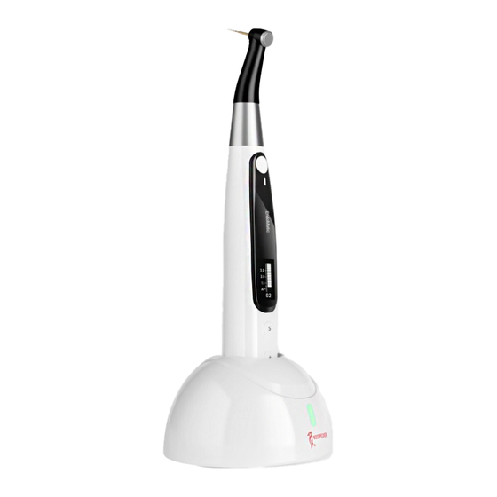
Ultrasurgery, Endo Motor, etc. 1.2 Product description EndoMatic is mainly used in Endodontic treatment. It is a cordless endo motor with root canal measurement capability. It can be used as a endo motor for preparation and enlargement of root canals, or device for measuring canal length. - Page 4 1.5 Scope of application 1.5.1 The device can be used for preparation and enlargement of root canals, or device for measuring canal length. dentists. 1.6 Contraindication Patients with implanted pacemakers (or other electrical equipment) who are warned not to use household appliances such as electric razors, hair dryers, etc.
- Page 5 1.7.3 Do not directly or indirectly place this device near heat source. Operate and store this device in reliable environment. 1.7.4 This device requires special precautions regarding electromagnetic compatibility (EMC) and must be in strict accordance with the EMC information for installation and use. Do not use this equipment especially in the vicinity of fluorescent lamps, radio transmitting devices, remote control devices, handheld and mobile high- frequency communication devices.
-
Page 6: Installation
1.8.1 Type of operation mode: Continuous operating device 1.8.2 Type of protection against electric shock: Class II equipment with internal power supply 1.8.3 Degree of protection against electric shock: B type applied part 1.8.4 Degree of protection against harmful ingress of water: Ordinary equipment (IPX0) 1.8.5 Degree of safety application in the presence of a flammable anesthetic mixture with air, oxygen, or nitrous oxide: Equipment cannot... - Page 7 Charging base Spray nozzle Power adapter Built-in Electrode Measuring wire File clip Lip hook Touch probe 2.2 Display Screens 2.2.1 Display Screens for 5 Operation Modes and Standby 2.2.1.1 EAL Mode This mode is for canal measurement. The motor handpiece does not run in this mode .
- Page 8 2.2.1.3 CCW Mode The motor handpiece rotates counterclockwise direction only. This mode is used to inject calcium hydroxide and other medicant. When this mode is being used, a double-beep sounds continuously. 2.2.1.4 REC Mode Recprocating mode. F: Forward angle, R: Reverse angle Adjustable every 10 degrees, adjustment range: 30º-340º.
- Page 9 rotation. Trigger torque: 0.4Ncm, 0.6Ncm, 0.8Ncm, 1Ncm Speed: 150rpm, 300rpm, 500rpm 2.2.2 Torque Display This appears when the motor is running. Meter shows the torque load 2.2.3 Canal Measurement Display This appears when a file is inside the canal and the lip hook is tip.
- Page 10 (0.20MPa~0.23MPa)). 2.3.3 The contra angle can only be used cooperatively with this device. Otherwise the contra angle will be damaged. 2.4 Installation and removal of contra angle. 2.4.1 Installation Line up the notch inside the contra angle with the projection inside the motor handpiece and slide it in until it clicks securely into place.
- Page 11 Warnings: motor handpiece. has been well installed. c) The contra angle does not rotate freely. Do not try to rotate it past its stopper. head. Hold down the push button on the contra angle and insert the file. angle. Warnings: After plugging the file into contra angle, let go the hand on push Inserting and removing files without holding the push button may damage the chuck of contra angle.
- Page 12 Warnings: stopped. Removing files without holding the push button will damage the chuck of contra angle. 2.6 Canal measurement functional connection This is not required if the canal measurement function will not be used. Connect the measuring wire to the motor handpiece. Line up the measuring wire plug with the notch on the back of the motor and push it all the way in.
- Page 13 Warnings: Connect the lip hook to the socket (white) on the measuring wire. Otherwise, the function of root canal preparation and root canal length measurement cannot be used together. Make sure the screw is tight enough. Otherwise, it might come out and be swallowed.
-
Page 14: Function And Operation Of Product
3 Function and operation of product a. Turn power on Press Main button to turn on motor handpiece. motor handpiece. c. Customized program change d. Parameter setting e. Preset program selection f. Handpiece functions setting and press Main button to entry handpiece functions setting, press Setting... - Page 15 3.2 Screen display Standby interface a. Customized program sequence number 0-9, totally 10 programs. b. Battery consumption c. Set speed d. Set torque e. Operation mode Working interface a. Set speed b. Set torque c. Real time torque d. Torque display scale Canal measurement mode interface b.
- Page 16 Apical reference point setting interface b. Apical foramen near physiological apical foramen. Clockwise rotation, forward ration Counter clockwise rotation, reverse rotation hydroxide and other solutions Reciprocating motion angle. Adaptive torque reverse Up to setting torque, the motor will move with reciprocating ATR mode ;...
-
Page 17: Operation Instruction
Auto Start is inserted in the canal. Apical Slow Down approaches the apex. Activating in CW and CCW operation mode. 5 operation modes for canal shaping and Operation Mode measurement. Such as CW, CCW, REC, ATR and EAL. Speed File rotation speed. For CW and CCW modes, the torque value Torque (Torque Limit) that triggers reverse rotation. - Page 18 operation. The motor handpiece will also automatically shut down while it is put into the charging base. 4.2 Selecting customized program sequence number The motor handpiece has 10 memory programs(M0-M9) and 5 preset sequence number during standby state. M0-M9 is a memory program for canal shaping and measurement, every memory program has its own parameters such as Operation mode, speed and torque, all these parameters can be changed.
- Page 19 The speed setting can be adjusted from 100 rpm to1000 rpm. decrease speed. Long press to fast increase or fast decrease speed. In ATR mode, speed of 150rpm, 300rpm and 500rpm are available. In REC mode, the speed is not optional. The torque setting can be adjusted from 0.4Ncm to 5Ncm.
- Page 20 inserted into the canal and the canal length indicator bar lights up more than 2 bars. into the canal. The Main button is used to start and stop the motor handpiece. ON: Motor starts automatically. This is the reference point where various apical actions are triggered.
- Page 21 Forward Angle: only activating in REC and ATR operation mode. Reverse Angle: only activating in REC operation mode. F: Forward Angle R: Reverse Angle adjustable every 10 degrees. forward angle and reverse angle should be greater than or equal to 120 degrees, otherwise, Forward Angle<Reverse Angle, such as F: 30º/ W3-ONE.
- Page 22 The parameters of "W3-Pro"can also be changed will be 4 corners around the Parameter. If want to change back to default setting, long during standby state, select "W3-Pro" and press will be reloaded, and the 4 corners around will disappear. Changing the preset program default setting separate.
- Page 23 Hand" can be change, press Adjusting button button to calibration. Before calibrating, making sure the original contra angle is installed, and do not install the without original contra angle or any load on After replacement of contra angle, the contra angle shall be calibrated before use.
- Page 24 2. In REC mode, when the load value is higher than preset torque value, if Forward angle is greater than Reverse angle, the file rotation automatically change to reverse rotation, and if Forward angle is less than Reverse angle, the file rotation automatically change to forward rotation.
- Page 25 Motor combined canal measurement function mode When using motor combined canal measurement function, the measuring wire must be connecting with motor handpiece by USB socket, and white socket connects with patient’s lip by lip hook, keep the black socket idle. The canal length indicator bar will show on the screen (more information about canal length...
- Page 26 Replacing Built-in Electrode If the canal length indicator bars in the meter do not light up when cleaning the rotor axle and built- in electrode does not solve the problem, then the built-in electrode is worn out and must be replaced with a new one according to the following procedure.
- Page 27 4.8 Canal measurement operation When using as alone apex locator mode. We suggest put the motor handpiece on the charging base to get better visual angle. standby state, press Adjusting button the explanations of Operation modes.) The measuring wire must be connecting with motor handpiece by USB socket, white socket connects with patient’s lip by lip hook, and black socket connect...
- Page 28 Connection testing Strongly recommend check the connection testing every time before use. Clip the holder onto lip hook and check that all the bars on the meter on the screen light up, otherwise, the replace. Root Canals not suitable for canal measurement Accurate measurement cannot be obtained if the root canal conditions shown below.
- Page 29 the opening of the root canal and contacts the gums, this will result in electrical leakage and an accurate measurement cannot be obtained. Wait for bleeding to stop completely. Clean the inside and opening of the canal throughly to get rid of all blood, and then make a measurement.
- Page 30 percha The gutta-percha must be completely removed to eliminate its insulating the apical foramen and then put a little saline in the canal, but do not let it Crown or metal prosthesis touching gingival tissue Accurate measurement cannot be prosthesis that is touching gingival tissue.
- Page 31 The actual apex for the canal is not the same as that for the anatomical apex. There are frequently cases where the apical foramen is located up towards the crown. In these cases, an X-ray might apex even though it has actually reached the apical foramen.
-
Page 32: Troubleshooting
part. 3. Vertically place the end part of contra angle more than 30 minutes to let go the redundant oil under gravity. Warnings Cautions to safely hold the contra angle while greasing. b: Do not use a swirling nozzle. Swing nozzle can only be used for injection of gas, not for oiling. -
Page 33: Cleaning, Disinfection And Sterilization
The time of endurance Battery capacity Please contact becomes shorter after becomes smaller. local distributor or charging. manufacturer. No sound Beeper Volume set to 0. Set Beeper Volume to Vol.0: Mute. 1,2,3. The continuously Choose CCW Mode, setting. start the motor the root canal. - Page 34 Health Canada. 6.2.9 To sterilize the endodontic files, refer to the manufacturer's instructions for use. 6.2.10 The contra angle needs to be lubricated after cleaning and disinfection, but before sterilization. 6.3 Step-by-Step Procedure # Operation Operating Mode Warning 1 Preparation Remove accessories (contra angle, lip...
- Page 35 # Operation Operating Mode Warning 4 Packaging Pack the - Check the validity period of the accessories pouch given by the manufacturer to (contra angle, lip determine the shelf life. - Use packaging which is resistant touch probe) in to a temperature up to 141°C "Sterilization (286°F) and in accordance with EN pouches".
-
Page 36: Storage, Maintenance And Transportation
7 Storage, maintenance and transportation 7.1 Storage 7.1.1 This equipment should be stored in a room where the relative humidity is 10% ~ 93%, atmospheric pressure is 70kPa to106kPa, and the temperature is -20°C ~ +55°C. 7.1.2 Avoid the storage in a too hot condition. High temperature will shorten the life of electronic components, damage battery, reshape or melt some plastic. -
Page 37: After Service
9 After service From the date this equipment has been sold, based on the warranty card, we will repair this equipment free of charge if there are quality problems. Please refer to the warranty card for the warranty period. 10 Symbol instruction Refer to instrucion Serial number manual/booklet... -
Page 38: Emc-Declaration Of Comformity
Technical Description Concerning Electromagnetic Emission Table 1: Declaration - electromagnetic emissions Guidance and manufacturer’s declaration - electromagnetic emissions The model EndoMatic is intended for use in the electromagnetic environment that it is used in such an environment. Emissions test Compliance... - Page 39 0.5 cycle <5 % UT environment. If the user variations on <5 % UT (>95% dip in UT.) of the models EndoMatic power supply (>95% dip in for 1 cycle requires continued input lines UT.) 70% UT...
- Page 40 Conducted RF & Radiated RF Guidance & Declaration - Electromagnetic immunity The model EndoMatic is intended for use in.the electromagnetic environment assure that it is used in such an environment. Immunity test IEC 60601 Compliance Electromagnetic environment - test level...
- Page 41 AM and FM radio broadcast and TV broadcast cannot be predicted theoretically with accuracy. in the location in which the model EndoMatic is used exceeds the applicable RF compliance level above, the model EndoMatic should be observed to verify normal operation.
- Page 42 For transmitters rated at a maximum output power not listed above, the recommended separation distance d in meters (m) can be estimated using the equation applicable to the frequency of the transmitter, where P is the maximum output power rating of the transmitter in watts (W) accordable to the transmitter manufacturer.
Need help?
Do you have a question about the EndoMatic and is the answer not in the manual?
Questions and answers