
Related Manuals for Mobius M9

Summary of Contents for Mobius M9
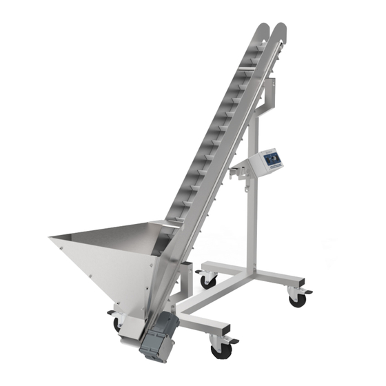
- Page 1 MOBIUS M9 AUTOFEED CONVEYOR USER GUIDE © 2 0 2 1 E T E R O S T E C H N O L O G I E S I N C . A L L R I G H T S R E S E R V E D .
- Page 2 CONTENTS...
-
Page 3: Table Of Contents
SAFETY SAFETY INSTRUCTIONS DISCLAIMER WARNING LABELS SERVICE & REPAIRS GENERAL SAFETY PRECAUTIONS INITIAL SETUP GET TO KNOW YOUR CONVEYORS WHAT'S IN THE CRATE INITIAL ASSEMBLY & INSPECTION OPERATIONS GENERAL OPERATION BEARING REPLACEMENTS CLEANING & MAINTENANCE CLEANING THE CONVEYORS PREVENTATIVE MAINTENANCE SPECIFICATIONS N OTES : This User Guide is a comprehensive manual covering the operation and maintenance of the Infeed... -
Page 4: Safety
SAFETY... -
Page 5: Safety Instructions
User Guide. The conveyor must be inspected regularly for damage, component failure and wear. Results of inspection activity should be documented. ETEROS TECHNOLOGIES makes every effort to ensure the M9 Autofeed is compliant with all current safety standards. It is the responsibility of the owner to ensure all municipal, provincial, state, county, territorial, and federal codes, regulations and standards have been met in each working location. -
Page 6: Warning Labels
Repairs may only be carried out by Eteros Technologies or a designated authorized agent (service technician). Should the need arise, please notify us: ETEROS TECHNOLOGIES 26 Industrial Ave. Carleton Place, Ontario, Canada K7C 3T2 www.eteros.com Improper interfacing, improper repair, or unauthorized modification could result in void warranty claims. MOBIUS CONVEYOR USER GUIDE... -
Page 7: General Safety Precautions
GENERAL SAFETY PRECAUTIONS 1. READ and become familiar with the entire User Guide. LEARN the equipment applications, limitations, and possible hazards. 2. DO NOT USE THE DEVICE IN A DANGEROUS ENVIRONMENT or damp or wet locations. Never expose the control panel directly to rain or water. Keep the work area well illuminated. 3. -
Page 8: Initial Setup
INITIAL SETUP... -
Page 9: Get To Know Your Conveyors
GET TO KNOW YOUR CONVEYORS © 2 0 2 1 E T E R O S T E C H N O L O G I E S I N C . A L L R I G H T S R E S E R V E D . M O B I U S T R I M M E R . -
Page 10: What's In The Crate
2 x 1" BUTTON HEAD SCREWS 6 x 3/8" BUTTON HEAD SCREWS 4 x 5/8" BUTTON HEAD SCREWS 2 x SIDE PANELS 2 x HOPPER HANDLES 6 x ACORN NUTS 1 x TENSIONING TOOL 2 x SUPPORT BAR MOBIUS CONVEYOR USER GUIDE... -
Page 11: Initial Assembly & Inspection
INITIAL ASSEMBLY & INSPECTION 1. Inspect the crate and crate contents to ensure no damage occurred during shipping. 2. Remove components from the crate. 3. Begin by installing the SHORT H-BASE UPRIGHT to the H-BASE by using 2 x 2” HEX BOLTS, 2 x WASHERS and 2 x NUTS. - Page 12 4. Install the TALL H-BASE UPRIGHT to the H-BASE using the same hardware in the last step.
- Page 13 5. Slide 2 x THROUGH SUPPORT BARS through the conveyor body. Then, slide 2 x THROUGH STOPS on to the protruding ends of the THROUGH SUPPORT BARS. Ensure the lip on the THROUGH STOPS is flush with the sheet metal. With the THROUGH STOPS installed, and with the help of another person, slide the protruding bars into the SHORT H-BASE UPRIGHT and TALL H-BASE UPRIGHT and fasten with 2 x 1”...
- Page 14 © 2 0 2 1 E T E R O S T E C H N O L O G I E S I N C . A L L R I G H T S R E S E R V E D . M O B I U S T R I M M E R . C O M MOBIUS CONVEYOR USER GUIDE...
- Page 15 7. Install a SIDE PANEL on each side of the conveyor by aligning the circular cutouts with the THROUGH STOPS and THROUGH BARS. Simply slide each panel down onto the pucks to install it on the conveyor.
- Page 16 © 2 0 2 1 E T E R O S T E C H N O L O G I E S I N C . A L L R I G H T S R E S E R V E D . M O B I U S T R I M M E R . C O M MOBIUS CONVEYOR USER GUIDE...
- Page 17 9. Finally, to complete the hopper assembly, install the BACK PLATE on to the outside of the side panels by aligning the screw holes and securing with 6 x ⅜” BUTTON HEAD SCREWS. The screw heads should go on the inside of the hopper, and the 6 x ACORN NUTS can be used on the outside to firmly secure the BACK PLATE.
-
Page 18: Operations
OPERATIONS... -
Page 19: General Operation
CON TR O L PAN E L A DJ US TM EN T For ease of use with other Mobius equipment, the orientation of the control panel can be reversed so that it can be accessed from either side of the equipment. To switch the control panel: 1. - Page 20 4. Flip the power switch to the ON position. 5. Flip the direction switch to set the conveyor to the correct travel direction. 6. Turn the speed adjustment knob clockwise to increase the belt speed, or counterclockwise to reduce the belt speed. MOBIUS CONVEYOR USER GUIDE...
-
Page 21: Bearing Replacements
BEARING REPLACEMENT Should the need arise to replace the bearings in your M9 Autofeed Conveyor, the process is straightfor- ward and involves little more than removing some screws. Follow along with the steps below and you’ll have your conveyor back up and running in no time! T O R EP L A CE B E A RI NG S ON T HE T EN SI ON I NG SID E OF YOUR AUT OF EED CO NVEYOR 1. - Page 22 6. Using a 5/32 hex key, remove the 4 screws securing the plate to the two side arms. 7. Using a 9/64 hex key, remove the flathead screw from the round bar that spans across the tensioning assembly on the side with the problematic bearing. MOBIUS CONVEYOR USER GUIDE...
- Page 23 8. With the plate removed, separate the side arm with the problematic bearing. Remove the bearing, and install your new bearing in the bore. Then, reinstall the plate you removed in the previous step. NOTE: if the problematic bearing is in the arm on the right (pictured below), there are two additional screws that need to be removed.
- Page 24 1. Remove the side panels and belt as per steps 1 and 2 of the previous section. 2. Remove the 4 bolts securing the motor to the conveyor using a 6mm hex key, then slide the entire motor off the drive shaft and set aside. MOBIUS CONVEYOR USER GUIDE...
- Page 25 3. Using a 9/64 hex key, remove the 4 bolts securing the motor assembly to the conveyor body. Removie the motor and set these aside in a safe place. 4. Grab the roller and slide the entire motor assembly out of the conveyor body. You may have to wiggle the assembly back and forth slightly as you pull it out.
- Page 26 © 2 0 2 1 E T E R O S T E C H N O L O G I E S I N C . A L L R I G H T S R E S E R V E D . M O B I U S T R I M M E R . C O M MOBIUS CONVEYOR USER GUIDE...
-
Page 27: Cleaning & Maintenance
CLEANING & MAINTENANCE... -
Page 28: Cleaning The Conveyors
© 2 0 2 1 E T E R O S T E C H N O L O G I E S I N C . A L L R I G H T S R E S E R V E D . M O B I U S T R I M M E R . C O M MOBIUS CONVEYOR USER GUIDE... -
Page 29: Specifications
Matte White Polyurethane Speed Adjustments 1-11 Belt Length 77” Belt Width 5” Motor 1/10 HP Power Requirements 110 V, 1.5 A Tools Mobius tensioning tool (included) Fits through standard door? Length 66 - 1/2" Height 65 - 1/4" Width 26 - 1/4"... - Page 30 Eteros Technologies West Eteros Technologies East 202-17665 66A Ave. 26 Industrial Ave. Surrey, BC Carleton Place, ON V3S 2A7 K7C 3T2 1-866-874-6264 INFO@MOBIUSTRIMMER.COM MOBIUSTRIMMER.COM...
Need help?
Do you have a question about the M9 and is the answer not in the manual?
Questions and answers