
Subscribe to Our Youtube Channel
Related Manuals for Enerpac PowaPak ZA4T Series


Summary of Contents for Enerpac PowaPak ZA4T Series
- Page 1 ZA4T-Series PowaPak™ Bolting Pump Instruction Sheet Model ZA4208TX-QR0P L4463 REV. C 07/20...
-
Page 2: Table Of Contents
TABLE OF CONTENTS PAGE INTRODUCTION ............................3 SAFETY ............................... 3 PRODUCT DATA ............................5 MAJOR FEATURES AND COMPONENTS ....................7 PRODUCT DESCRIPTION .......................... 8 PREPARATION FOR USE ........................... 8 LIFTING AND TRANSPORTING ....................... 11 OPERATION .............................. 11 MAINTENANCE ............................13 10.0 TROUBLESHOOTING .......................... -
Page 3: Introduction
/ or damage to other property. use with hydraulic torque wrenches in industrial bolting Enerpac cannot be responsible for any damage or injury applications. Refer to Sections 4.0 and 5.0 of this manual from unsafe use, lack of maintenance, or incorrect for additional product information and details. - Page 4 • Immediately replace worn or damaged parts. Use only genuine Enerpac parts from approved NOTICE distributors or service centers. Enerpac parts have been engineered for proper fit and function and safe • Hydraulic equipment must only be serviced by a operation.
-
Page 5: Product Data
Enerpac Spin-On hydraulic couplers are included with pump. Pump hydraulic port thread size is 1/4” NPTF (couplers removed). Approximate usable oil capacity of pump hydraulic reservoir. Pump total oil capacity (including reservoir and pump element) is approximately 1.86 gallons [7 liters]. - Page 6 3.3 External Dimensions - Model ZA4208TX-QR0P Dimension Item inch 20.5 19.7 12.5 20.0 (pendant cable length) L4463 (...
-
Page 7: Major Features And Components
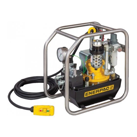
4.0 MAJOR FEATURES AND COMPONENTS Key: 1. Lifting Eye 2. Air Pressure Gauge 3. Air Inlet Connection (1/2" NPTF) 4. Air Exhaust Muffler 5. Hyd. Relief Valve (user-adjustable) 6. Air Motor 7. Reservoir Air Breather 8. Hydraulic Reservoir 9. Hydraulic Control Valve Manifold 10. -
Page 8: Product Description
The hydraulic reservoir is pre filled with oil at the factory. 5.1 Introduction However, the oil level should always be checked as a The Enerpac ZA4T-Series air-powered bolting pump is precaution before running the pump. See Figure 3 and designed for use with hydraulic torque wrenches rated at refer to the following steps: 10,000 psi [690 bar] maximum operating pressure. - Page 9 NOTICE installed in the hydraulic manifold ports. These coupler Refer to Sections 6.5 and 9.4 of this manual for additional halves are compatible with Enerpac THQ Series torque information regarding the air filter/regulator. Also refer wrench hoses (sold separately). to the air filter/regulator manufacturer’s instructions as necessary.
- Page 10 6.5 Air Filter/Regulator and Lubricator Precautions Add oil to the air lubricator as described in the following steps: CAUTION Failure to follow the following precautions Shut off compressed air supply. Disconnect air and instructions could allow the air filter/regulator and/or supply line from air inlet connection on pump.
-
Page 11: Lifting And Transporting
6.7 Air Lubricator - Oil Drip Rate Adjustment The air lubricator drip rate must be adjusted before torque wrench is used on nut or bolt. See Figure 6. To make an initial adjustment: Be sure that the torque wrench is NOT mounted on a nut or bolt. - Page 12 8.2 Operating Instructions 1. Press and hold The pump is operated by a two-button remote control red button. pendant. See Figure 8. • Press and hold the green ON/ADV button to start the pump and advance the wrench. The button must remain pressed to advance the wrench.
-
Page 13: Maintenance
Shut off the pump compressed air supply. Be certain that the air filter/regulator pressure gauge indicates zero (0) psi/bar. At pump hydraulic ports “A” and “B”, loosen the threaded collars on the female couplers. Disconnect hoses from pump. To prevent contamination, install dust covers over pump and hose couplers. - Page 14 Connected Section 9.2. • When adding oil or refilling the hydraulic reservoir, use only Enerpac HF hydraulic oil. Use of other oils may result in damage to pump components and may Disconnected void the Enerpac product warranty.
- Page 15 Tube Color: D. GREEN Key: 1. Intake Hose 2. Hose Clamp (From 3. Elbow Y-Connector See Figure 13) Figure 14: Air Tube Connection - Hyd. Control Valve Figure 15: Air Motor Intake Hose Key: 1. Air Logic Control Valve 5. Support Bracket 2.
- Page 16 Key: 1. Roll Cage 2. Capscrews 3. Pump Key: 1. Capscrew 2. Gasket 3. Pump Assy. 4. Reservoir Gasket 5. Hyd. Reservoir Figure 17: Pump and Roll Cage Remove four capscrews securing the roll cage to the hydraulic reservoir. See Figure 17. Carefully position the pump through the open side of the roll cage until it is completely removed.
- Page 17 9.3 Air Exhaust Muffler The pump is equipped with an air exhaust muffler that helps maintain quiet pump operation. See Figure 20. Always shut off compressed air supply and disconnect air supply hose from pump before performing any maintenance or repairs on the muffler. Periodically check the muffler bowl for condensate accumulation.
- Page 18 9.4 Air Filter/Regulator Maintenance 9.5 Air Lubricator Maintenance Always shut off compressed air supply Always shut off compressed air supply and CAUTION CAUTION and disconnect air supply hose from pump before disconnect air supply hose from pump before removing removing the air filter bowl or air lubricator bowl for any the air lubricator bowl for any reason.
-
Page 19: Troubleshooting
10.0 TROUBLESHOOTING Only qualified hydraulic maintenance personnel with appropriate skills and training should be permitted to service the pump or system components. The Troubleshooting Chart is not all inclusive but is intended to be used as a guide to help diagnose and resolve the most common problems which may occur. Troubleshooting Chart Symptom Possible Cause... - Page 20 Troubleshooting Chart (continued) Symptom Possible Cause Solution 5. Torque wrench advances a. Air in the hydraulic system. Advance and retract the torque wrench until operation is or retracts erratically. smooth. Refer to Section 8.4. b. Low air pressure and/or flow. Increase air pressure as required.
- Page 21 NOTES _______________________________________________________________________________________ _______________________________________________________________________________________ _______________________________________________________________________________________ _______________________________________________________________________________________ _______________________________________________________________________________________ _______________________________________________________________________________________ _______________________________________________________________________________________ _______________________________________________________________________________________ _______________________________________________________________________________________ _______________________________________________________________________________________ _______________________________________________________________________________________ _______________________________________________________________________________________ _______________________________________________________________________________________ _______________________________________________________________________________________ _______________________________________________________________________________________ _______________________________________________________________________________________ _______________________________________________________________________________________ _______________________________________________________________________________________ _______________________________________________________________________________________ _______________________________________________________________________________________ _______________________________________________________________________________________ _______________________________________________________________________________________ _______________________________________________________________________________________ L4463 (...
- Page 22 NOTES _______________________________________________________________________________________ _______________________________________________________________________________________ _______________________________________________________________________________________ _______________________________________________________________________________________ _______________________________________________________________________________________ _______________________________________________________________________________________ _______________________________________________________________________________________ _______________________________________________________________________________________ _______________________________________________________________________________________ _______________________________________________________________________________________ _______________________________________________________________________________________ _______________________________________________________________________________________ _______________________________________________________________________________________ _______________________________________________________________________________________ _______________________________________________________________________________________ _______________________________________________________________________________________ _______________________________________________________________________________________ _______________________________________________________________________________________ _______________________________________________________________________________________ _______________________________________________________________________________________ _______________________________________________________________________________________ _______________________________________________________________________________________ _______________________________________________________________________________________ L4463 (...
- Page 23 NOTES _______________________________________________________________________________________ _______________________________________________________________________________________ _______________________________________________________________________________________ _______________________________________________________________________________________ _______________________________________________________________________________________ _______________________________________________________________________________________ _______________________________________________________________________________________ _______________________________________________________________________________________ _______________________________________________________________________________________ _______________________________________________________________________________________ _______________________________________________________________________________________ _______________________________________________________________________________________ _______________________________________________________________________________________ _______________________________________________________________________________________ _______________________________________________________________________________________ _______________________________________________________________________________________ _______________________________________________________________________________________ _______________________________________________________________________________________ _______________________________________________________________________________________ _______________________________________________________________________________________ _______________________________________________________________________________________ _______________________________________________________________________________________ _______________________________________________________________________________________ L4463 (...
- Page 24 © 2020 Enerpac, All Rights Reserved.
Need help?
Do you have a question about the PowaPak ZA4T Series and is the answer not in the manual?
Questions and answers