Table of Contents
Advertisement
Available languages
Available languages
Quick Links
I N S T A L L A T I O N I N S T R U C T I O N S
I N S T R U C C I O N E S D E I N S T A L A C I Ó N
Elevador automatizado para televisor
This device complies with part 15 of the FCC rules. Operation is subject to the following 2 conditions: (1) This device may not cause harmful
interference, and (2) this device must accept any interference received, including interference that may cause undesired operation.
This equipment has been tested and found to comply with the limits of a Class B digital device, pursuant to Part 15 of the FCC rules. These limits are
designed to provide reasonable protection against harmful interference in a residential installation. This equipment generates, uses and can radiate
radio frequency energy, and if not installed and used in accordance with the instructions, may cause harmful interference to radio or television
communications. However, there is no guarantee that the interference will not occur in a particular installation. If this equipment does cause harmful
interference to radio or television reception, which can be determined by turning the equipment off and on, the user is encouraged to try to correct
the interference by one of the following measures:
•
Reorient or relocate the receiving antenna
•
Increase the separation between the equipment and receiver
•
Connect the equipment to an outlet on a circuit other than that to which the receiver is connected
Consult the dealer or and experienced radio/TV technician for help
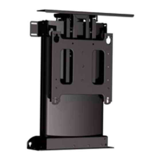
Automated Display Lift
CM2L40
Advertisement
Chapters
Table of Contents

Related Manuals for CHIEF CM2L40U


Summary of Contents for CHIEF CM2L40U
- Page 1 I N S T A L L A T I O N I N S T R U C T I O N S I N S T R U C C I O N E S D E I N S T A L A C I Ó N Automated Display Lift Elevador automatizado para televisor This device complies with part 15 of the FCC rules.
- Page 2 CM2L40 Installation Instructions Milestone AV Technologies, and its affiliated corporations and subsidiaries (collectively, "Milestone"), intend to make this manual accurate and complete. However, Milestone makes no claim that the information contained herein covers all details, conditions or variations, nor does it provide for every possible contingency in connection with the installation or use of this product.
-
Page 3: Table Of Contents
Installation Instructions CM2L40 CONTENTS INSTALLATION REQUIREMENTS ......................6 Power Requirements and Wiring ....................... 6 INSTALLATION ............................6 Pre-Installation Configuration and Adjustments ..................6 Configuring the Mount for the Display ....................6 Display Installation ..........................8 Shelf Height Adjustment ......................... 9 Determining Minimum I.D. - Page 4 CM2L40 Installation Instructions DIMENSIONS SHELF BRACKET MOUNTING HOLES (2) SIDE MOUNTING BRACKETS (1 PER SIDE) 2.50 APPROX. 40" OF TRAVEL 28.38 28.17 NOTES: THE CUSTOM INTERFACE BRACKET REQUIRED 19.00 FOR YOUR FLAT PANEL (NOT SHOWN) WILL ADD 1/2" TO 2" IN DEPTH AND MAY AFFECT THE LOCATION OF THE FLAT PANEL ON THE MOUNT.
- Page 5 Installation Instructions CM2L40 LEGEND Tighten Fastener Pencil Mark Apretar elemento de fijación Marcar con lápiz Loosen Fastener Drill Hole Aflojar elemento de fijación Perforar Phillips Screwdriver Adjust Destornillador Phillips Ajustar Open-Ended Wrench Remove Llave de boca Quitar By Hand Optional A mano Opcional Hex-Head Wrench...
-
Page 6: Installation Requirements
CM2L40 Installation Instructions INSTALLATION REQUIREMENTS Record measurement. The CM2 has been designed to be mounted into a cabinet or similar type of furnishing. WARNING: IMPROPER INSTALLATION CAN LEAD TO LIFT TIPPING CAUSING SEVERE PERSONAL INJURY OR DAMAGE TO EQUIPMENT! It is the installers responsibility to make certain the structure to which the lift is being mounted is capable of supporting 4 times the weight of the lift and all attached equipment. - Page 7 Installation Instructions CM2L40 Secure faceplate to faceplate mounting bracket using two locknuts. (See Figure 5) Figure 5 10. Using the remote control, lower the lift until it stops. (See Figure 3) If more than 2" of faceplate adjustment is required: 11.
-
Page 8: Display Installation
CM2L40 Installation Instructions 15. Align studs in faceplate with appropriate holes in faceplate mounting bracket and hang faceplate on bracket with studs. WARNING: IMPROPER INSTALLATION CAN LEAD TO 16. Secure faceplate to faceplate mounting bracket using two MOUNT FALLING CAUSING SEVERE PERSONAL INJURY locknuts. -
Page 9: Shelf Height Adjustment
Installation Instructions CM2L40 NOTE: Verify that there is at least 1" of clearance between bottom of display and mount base. If there is less than 1" of clearance, remove the display and refer to Adjusting Faceplate Location section, and adjust display height accordingly. -
Page 10: Determining Minimum I.d. Of Furniture
CM2L40 Installation Instructions NOTE: With the mount configured for the display and the display installed, it is now possible to calculate the Cover minimum I.D of the cabinet. Determining Minimum I.D. of Furniture Measure and record distance "A". (See Figure 16) Measure and record distance "B". -
Page 11: Cable Installation And Routing
Installation Instructions CM2L40 Cable Installation and Routing The CM2 has an integrated cable management system that allows cables to be automatically "fed out" as the lift raises, and "reeled in" as the lift lowers while maintaining constant cable tension. IMPORTANT ! : The CM2 requires minimum cable lengths of Cable guide 8 feet from display through lower mount. - Page 12 CM2L40 Installation Instructions From Display Upper cable clamp Do NOT use cable ties within area inside dotted line! Lower cable clamps Figure 19...
- Page 13 Installation Instructions CM2L40 15. Slide cable guide side cover over CM2 mount lining up two holes in cable guide side cover with two holes in CM2 mount. (See Figure 21) Cable guide side cover Cable pulley center shaft Figure 20 Figure 21 Route cables under cable pulley and up over top of cable 16.
-
Page 14: Mount Installation
CM2L40 Installation Instructions Mount Installation Mark eight base mounting hole locations. (See Figure 24) Drill pilot holes at marked locations. The CM2 has been designed to be mounted into a cabinet or Mark four side bracket mounting hole locations. similar type of furnishing. (See Figure ) The following installation instructions assume a suitable 10. -
Page 15: Adjustments
Installation Instructions CM2L40 ADJUSTMENTS Display Travel Adjustment The CM2 is designed to allow the adjustment of both "Extend" and "Retract" display travel limits. The CM2 is shipped set at maximum extension and retraction. There is an upward travel limit adjustment screw and a downward travel limit adjustment screw located on the top right hand side of the mount. -
Page 16: Lift Column Bearing Adjustment
CM2L40 Installation Instructions Lift Column Bearing Adjustment The upper and lower lift columns are aligned using two lift bearings, one upper and one lower. Bearing adjustment is pre-set at the factory, however, there may be times when it is required to make slight adjustments in Upper Lift Column bearing tightness to eliminate excess play in lift columns or Bearing Adjustment Points... -
Page 17: Extended Programming Capabilities
Installation Instructions CM2L40 Extended Programming Capabilities The CM2 allows for extended programming to make the mount compatible with other devices such as a Universal Remote or other control devices through a serial connection. Setting or changing the configuration of the CM2 is done through the remote control provided with the mount. -
Page 18: Ir-Se15 Programming
CM2L40 Installation Instructions IR-SE15 Programming IR-SE15 Control Features: • Carrier Frequency: 38KHz • Protocol: NEC - Full Repeat • System Code(s): 6E (Default) - Multiple Codes Selected via Key-Press (see below) Table 1-1: IR-SE15 Control Codes Key Number Key Name Hex Code HOME SAVE... -
Page 19: Serial Communications
CM2L40 Serial Communications Address Description NOTE: Multiple Chief devices can be used on the same network by Check with the appropriate automation system vendor setting each device to a different address. for available drivers and/or software for any external devices. -
Page 20: Cm2 Hardware Reference
CM2L40 Installation Instructions 1st Position of switch array 1st Position of connector array 1st Position of connector array CM2 Connectors and Switches Figure 31 CM2 Interface Board Hardware Information (See Figure 31) Dry Contact Closures The unit provides dry contact outputs for system feedback, or to control other devices. To complete circuits to external devices: Connect the common wire from your switch to terminal 7. -
Page 21: Other Dry Contact Options
Installation Instructions CM2L40 Pin 1 Isolated Extend/Retract Input (+) Pin 2 Isolated Extend/Retract Input (-) Pin 3 Isolated Voltage Sense Input (+) Pin 4 Isolated Voltage Sense Input (-) Pin 5 24V DC Supply Out (150ma Max.) Pin 6 Ground Pin 7 RS485 Ref. - Page 22 Units are shipped with error contacts "Normally Open". To set unit to respond to "Normally Closed" error contacts contact a Chief Technical Support representative by calling 1-800-582-6480, or by visiting www.chiefmfg.com. When unit receives an Extend error signal during an extend operation, the unit will immediately stop and reverse direction.
-
Page 23: Connector And Switch Assignments
Installation Instructions CM2L40 Extend Limit Option Internal set of dry contacts close when unit is fully extended. Contact Rating: 30V AC or DC 1A max. (See Figure 31) and (See Figure 38) Figure 38 Retract Limit Option Internal set of dry contacts close when unit is fully retracted. Contact Rating: 30V AC or DC 1A max. -
Page 24: Troubleshooting
CM2L40 Installation Instructions Switch 1 Switch 2 Switch 3 Switch 4 Not Used Switch 5 Not Used Switch 6 485 Address Switch 7 485 Address Switch 8 485 Address IR System Code Select Logic Switch Settings (Sw 1-3) Select 2 Select 1 Select 0 IR System Code... - Page 25 I N S T R U C C I O N E S D E I N S T A L A C I Ó N Instrucciones de instalación Istruzioni di installazione Installationsanleitung Installatie-instructies Instruções de Instalação Instructions d´installation Elevador automatizado para televisor Este dispositivo cumple con la Sección 15 de las normas de la Comisión Federal de Comunicaciones (FCC, por sus siglas en inglés) de los Estados Unidos.
- Page 26 CM2L40 Instrucciones de instalación Milestone AV Technologies y sus filiales y compañías asociadas (conjuntamente, "Milestone") procuran que este manual sea preciso y esté completo. No obstante, Milestone no garantiza que la información aquí incluida proporcione todos los detalles, las condiciones o las variaciones existentes, ni contemple todas las posibles contingencias relacionadas con la instalación o el uso de este producto.
- Page 27 Instrucciones de instalación CM2L40 ÍNDICE REQUISITOS DE INSTALACIÓN ......................... 30 Requisitos de alimentación y cableado ......................30 INSTALACIÓN .............................. 30 Configuración y ajustes para la instalación ....................30 Configuración del soporte según el televisor elegido ................30 Instalación del televisor ...........................32 Ajuste de la altura del estante ......................... 33 Cálculo de la altura interna mínima del mueble ..................
- Page 28 CM2L40 Instrucciones de instalación SHELF BRACKET MOUNTING HOLES (2) SIDE MOUNTING BRACKETS (1 PER SIDE) 2.50 APPROX. 40" OF TRAVEL 28.38 28.17 NOTES: 19.00 THE CUSTOM INTERFACE BRACKET REQUIRED FOR YOUR FLAT PANEL (NOT SHOWN) WILL ADD 1/2" TO 2" IN DEPTH AND MAY AFFECT THE LOCATION OF THE FLAT PANEL ON THE MOUNT.
- Page 29 Instrucciones de instalación CM2L40 REFERENCIAS Tighten Fastener Pencil Mark Apretar elemento de fijación Marcar con lápiz Loosen Fastener Drill Hole Aflojar elemento de fijación Perforar Phillips Screwdriver Adjust Destornillador Phillips Ajustar Open-Ended Wrench Remove Llave de boca Quitar By Hand Optional A mano Opcional...
-
Page 30: Requisitos De Instalación
CM2L40 Instrucciones de instalación REQUISITOS DE INSTALACIÓN Mida la distancia que hay desde el centro de un perno de montaje inferior hasta el punto más bajo del televisor. El CM2 está diseñado para ser instalado en armarios o Anote la medida. muebles similares. - Page 31 Instrucciones de instalación CM2L40 Fije la placa frontal a su soporte de sujeción con dos tuercas de seguridad. (Consulte la Figura 6) Figura 5 10. Con el control remoto, baje el elevador hasta que se detenga. (Consulte la Figura 3) Si la placa frontal requiere un ajuste superior a 50,8 mm (2 pulgadas): 11.
-
Page 32: Instalación Del Televisor
CM2L40 Instrucciones de instalación 15. Alinee los pernos roscados de la placa frontal con los orificios correspondientes del soporte de sujeción de dicha placa y ADVERTENCIA: SI NO SE INSTALA CORRECTAMENTE, cuelgue la placa frontal en el soporte mediante los pernos. EL SOPORTE PUEDE CAERSE Y CAUSAR LESIONES 16. -
Page 33: Ajuste De La Altura Del Estante
Instrucciones de instalación CM2L40 NOTA: Instale el módulo del estante en los soportes de sujeción Verifique que haya una separación de 25,4 mm del estante alineando los pernos del soporte del estante (1 pulgada) como mínimo entre la parte inferior del con los clips de los soportes de ajuste del estante. -
Page 34: Cálculo De La Altura Interna Mínima Del Mueble
CM2L40 Instrucciones de instalación NOTA: Con el soporte configurado para el televisor elegido y el televisor instalado, ahora se puede calcular la altura interna mínima del armario. Cubierta Cálculo de la altura interna mínima del mueble Mida y anote la distancia "A" indicada en la figura de abajo. (Consulte la Figura 16) Mida y anote la distancia "B"... -
Page 35: Instalación Y Tendido De Cables
Instrucciones de instalación CM2L40 Instalación y tendido de cables El CM2 cuenta con un sistema integrado de organización de cables que automáticamente "desenrolla" los cables cuando el elevador sube y los "enrolla" cuando el elevador baja, manteniendo constante su tensión. IMPORTANTE: El CM2 requiere como mínimo 2,44 m (8 pies) de cable desde la pantalla hasta el soporte inferior. - Page 36 CM2L40 Instrucciones de instalación Proveniente del televisor Sujetador superior NO use cinchos sujetacables dentro del área delimitada por la línea de puntos Sujetadores inferiores Figura 19...
- Page 37 Instrucciones de instalación CM2L40 PRECAUCIÓN: SI AJUSTA LOS SUJETADORES DE CABLES EN EXCESO, PODRÍA APLASTAR LOS CABLES Y, EN CONSECUENCIA, DAÑAR EL EQUIPO. NO ajuste los sujetadores de cables en exceso. 14. Comenzando por el sujetador de cables superior y avanzando hacia abajo, tense los cables y ajuste los sujetadores inferiores.
-
Page 38: Instalación Del Soporte
CM2L40 Instrucciones de instalación Instalación del soporte Marque la ubicación de los ocho orificios de montaje de la base. (Consulte la Figura 24) El CM2 está diseñado para ser instalado en armarios o Realice los orificios según las marcas. muebles similares. Marque la ubicación de los cuatro orificios de montaje de Las siguientes instrucciones de instalación suponen que se las placas de sujeción laterales. -
Page 39: Ajustes
Instrucciones de instalación CM2L40 AJUSTES Ajuste del desplazamiento del televisor El CM2 cuenta con un mecanismo que permite ajustar los límites de desplazamiento del televisor. El CM2 se despacha configurado en los límites de ascenso y de descenso máximos. En el lateral superior derecho del soporte, hay un tornillo para ajustar el límite de desplazamiento ascendente y un tornillo para ajustar el límite de desplazamiento descendiente. -
Page 40: Ajuste De Los Cojinetes De Las Columnas De Elevación
CM2L40 Instrucciones de instalación Ajuste de los cojinetes de las columnas de elevación Las columnas de elevación superior e inferior están alineadas mediante dos cojinetes de elevación, uno superior y otro inferior. El ajuste de los cojinetes viene configurado de fábrica. No Puntos de ajuste de los cojinetes obstante, a veces es necesario hacer pequeños ajustes en la de la columna de elevación inferior... -
Page 41: Funciones De Programación Avanzadas
Instrucciones de instalación CM2L40 Funciones de programación avanzadas El CM2 cuenta con funciones de programación avanzadas para compatibilizar el soporte con otros equipos, tales como un control remoto universal u otros dispositivos de control, a través de una conexión en serie. Para configurar el CM2, se utiliza el control remoto provisto con el soporte. -
Page 42: Programación Del Control Remoto Se15
CM2L40 Instrucciones de instalación Programación del control remoto SE15 Funciones de control del SE15: • Frecuencia portadora: 38 kHz • Protocolo: NEC. Repetición completa. • Código(s) del sistema: 6E (predeterminado). Selección de otros códigos mediante los botones (ver a continuación). Tabla 1-1: Códigos de control del SE15: Número Nombre... -
Page 43: Comunicaciones En Serie
Instrucciones de instalación CM2L40 Comunicaciones en serie Descripción de dirección: Es posible utilizar varios dispositivos Chief en una misma red si NOTA: Consulte a un distribuidor de sistemas de se asigna a cada uno de ellos una dirección distinta. automatización respecto de software o controladores NOTA: Todas las unidades se despachan con la dirección... -
Page 44: Referencia Del Soporte Físico Del Cm2
CM2L40 Instrucciones de instalación posición del conjunto de interruptores posición del conjunto de conectores posición del conjunto de conectores Figura 31 Información sobre la placa de interfaz del CM2 (Consulte la Figura 31) Cierres de contactos secos La unidad cuenta con salidas de contactos secos para retroalimentación del sistema o para control de otros dispositivos. Para conectar dispositivos externos: Conecte el cable COMMON de su interruptor al terminal 7. -
Page 45: Otras Opciones De Contactos Secos
Instrucciones de instalación CM2L40 Pin 1 Entrada de descenso/ascenso aislada (+) Pin 2 Entrada de descenso/ascenso aislada (-) Pin 3 Entrada de detección de voltaje aislada (+) Pin 4 Entrada de detección de voltaje aislada (-) Pin 5 Salida de suministro de 24 V CC (150 mA máximo) Pin 6 Conexión a tierra Pin 7... - Page 46 NOTA: Las unidades se despachan con contactos de error "normalmente abiertos". Para configurar la unidad para que responda a contactos de error "normalmente cerrados", comuníquese con un representante de soporte técnico de Chief al 1-800-582-6480 o visite www.chiefmfg.com. Cuando la unidad recibe una señal de error de descenso durante una operación de descenso, se detiene de inmediato y asciende.
- Page 47 Instrucciones de instalación CM2L40 Opción de límite de extensión El conjunto de contactos secos internos se cierra cuando la unidad alcanza el límite de extensión. Régimen de trabajo del contacto: 30 V CA o CC 1 A máximo (Consulte la Figura 31 y la Figura 38) Figura 38 Opción de límite de retracción El conjunto de contactos secos internos se cierra cuando la unidad alcanza el límite de retracción.
-
Page 48: Soluci Ó N De Problemas
CM2L40 Instrucciones de instalación Interruptor 1 Interruptor 2 Interruptor 3 Interruptor 4 No se usa Interruptor 5 No se usa Interruptor 6 Dirección 485 Interruptor 7 Dirección 485 Interruptor 8 Dirección 485 Lógica de selección del código del sistema IR Configuración de interruptores (interruptores 1 a 3) Selección 2... - Page 49 Instrucciones de instalaci n Istruzioni di installazione Installationsanleitung Installatie-instructies Instru es de Instala o Instructions d installation FCC. : (1) FCC. • • • CM2L40...
- Page 50 CM2L40 Milestone AV Technologies «Milestone») . Milestone . Milestone » • • • • • • • • • • •...
- Page 51 CM2L40 ........................54 ................54 ..............................54 ..................54 ....................54 ..........................56 ........................57 ............58 ........................59 ..........................63 ..............................64 ......................64 ................64 ....................65 ..................65 ................66 IR-SE15 ........................67 ....................68 CM2 ......................... 69 CM2 ...............
- Page 52 CM2L40 SHELF BRACKET MOUNTING HOLES (2) SIDE MOUNTING BRACKETS (1 PER SIDE) 2.50 APPROX. 40" OF TRAVEL 28.38 28.17 NOTES: THE CUSTOM INTERFACE BRACKET REQUIRED 19.00 FOR YOUR FLAT PANEL (NOT SHOWN) WILL ADD 1/2" TO 2" IN DEPTH AND MAY AFFECT THE LOCATION OF THE FLAT PANEL ON THE MOUNT.
- Page 53 CM2L40 Tighten Fastener Pencil Mark Apretar elemento de fijación Marcar con lápiz Loosen Fastener Drill Hole Aflojar elemento de fijación Perforar Phillips Screwdriver Adjust Destornillador Phillips Ajustar Open-Ended Wrench Remove Llave de boca Quitar By Hand Optional A mano Opcional Hex-Head Wrench Security Wrench Llave de cabeza hexagonal...
- Page 54 CM2L40 (220/240 , 50 6" 16" (406 16" (406 5/16" 5/16" x 2 1/2" ( ). ( . 1) . 2. 2 = 19,5" 19,5" - 16" = 3,5" (...
- Page 55 CM2L40 1" . 3) (25 MM) . 3) . 6) . 4) . 4) . 3) 6. ( . 3) . 6) . 6)
- Page 56 CM2L40 CM2, 86,18 (190 . 7) 18,1...
- Page 57 CM2L40 . 10) . 9) . 10) . 9) . 10) . 11 . 10 . 12...
- Page 58 CM2L40 «A», . 16) «B», CM2. ( . 16) «C», . 16) . 13 (1/4 . 15) (1/4 . 15 . 14...
- Page 59 CM2L40 CM2, 86.18 (190 . 16 . 17)
- Page 60 CM2L40 CM2. . 19) . 20) • . 19) . 20) • . 19) . 20) . 17 . 19) . 19) . 20) . 18...
- Page 61 CM2L40 . 19...
- Page 62 CM2L40 . 19) . 19) CM2. ( . 16) . 20 . 19) . 20) . 19) . 20) . 19) . 20) . 19) . 20) . 21 . 19) . 20) . 19) . 20) . 19). . 19) .
- Page 63 CM2L40 . 22) . 23) . 24) . 24). . 22 . 23 . 24) . 24) . 24) 10° CM2: 18,1...
- Page 64 CM2L40 . 25 . 24 . 7. . 26) – . 25)
- Page 65 CM2L40 . 27 . 26 . 27) 3/16". ( . 27)
- Page 66 CM2L40 « » . 32) . 28 Universal Remote (20-30 AAA, : SE15 . 29...
- Page 67 CM2L40 IR-SE15 IR-SE15: • : 38 • : NEC – • : 6E ( ) – 1-1: IR-SE15 HOME ( SAVE ( UP ( LEFT ( STOP ( RIGHT ( DOWN ( PRESET 1 PRESET 2 PRESET 3 3 + 7 ( 12 –...
- Page 68 CM2L40 – 00. « » [PR] = (CM2 = 02) [AD] = [CR] = ASCII [CH] = [ST] = RS-485 REF RS-485 + RS-485 - ANSI TIA/EIA-485-A: 9600 (HEX) (HEX) (HEX) (HEX) (HEX) (HEX) (HEX) > • CM2L40: 02 • •...
- Page 69 CM2L40 . 31 . 31) « » 7. ( . 32) « » « » . 32...
- Page 70 CM2L40 . 150 RS485 RS485 (+) RS485 (-) . 31) . 34) . 33...
- Page 71 CM2L40 . 31) . 34) . 34 . 31) . 35) . 35 1-800-582-6480 www.chiefmfg.com. . 31) . 36) . 36...
- Page 72 CM2L40 1-800-582-6480 www.chiefmfg.com. . 31) . 37) . 37 : 30 . 1 . ( . 31) . 38) . 38 : 30 . 1 . ( . 31) . 39) . 39 ».
- Page 73 CM2L40 DIP- 1-3) RS485 6-8) RS485 • • « • » 10-15...
- Page 74 CM2L40...
- Page 75 CM2L40...
- Page 76 F 877.894.6918 / 952.894.6918 Europe A Fellenoord 130 5611 ZB EINDHOVEN, The Netherlands P +31 (0)40 2668620 Chief Manufacturing, a products division F +31 (0)40 2668615 of Milestone AV Technologies Asia Pacific A Office No. 1 on 12/F, Shatin Galleria...
Need help?
Do you have a question about the CM2L40U and is the answer not in the manual?
Questions and answers