
Related Manuals for Ancona AN-1160


Summary of Contents for Ancona AN-1160
- Page 1 MODEL: AN-1160 3 IMPORTANT SAFETY INSTRUCTIONS Carefully read the following important information regarding installation safety and maintenance. Keep these instructions for future reference.
-
Page 2: Important Safety Notice
IMPORTANT SAFETY NOTICE READ AND SAVE THESE INSTRUCTIONS READ ALL INSTRUCTIONS BEFORE INSTALLING AND OPERATING THIS APPLIANCE The installation in this manual is intended for qualified installers, service technicians or persons ● with similar qualified background. Installation and electrical wiring must be done by qualified professionals and in accordance with all applicable codes and standards, including fire-rated construction. - Page 3 IMPORTANT SAFETY NOTICE READ AND SAVE THESE INSTRUCTIONS READ ALL INSTRUCTIONS BEFORE INSTALLING AND OPERATING THIS APPLIANCE WARNING: TO REDUCE RISK OF A RANGE TOP GREASE FIRE: a) Never leave surface units unattended at high settings. Boilovers cause smoking and greasy spillovers that may ignite.
-
Page 4: Parts Supplied
PARTS SUPPLIED: 2 Filters... -
Page 5: Venting Requirements
VENTING REQUIREMENTS: HEIGHT & CLEARANCE: • Vent system must terminate to the outside (Roof or side wall). • DO NOT terminate the vent system in an attic Can reach 9’ ceiling or other enclosed area. if installed • DO NOT use 4” (10.2 cm) laundry-type wall at 31”... -
Page 6: Calculating Vent System Length
IMPORTANT: • ini u round or - rectangular duct (purchased separately) ust be used to aintain a i u airflow efficiency • Always use rigid type etal alu inu ducts if available to a i i e airflow when connecting to provided duct •... -
Page 7: Venting Methods
VENTING METHODS: • This range hood is factory set for venting through the roof or wall. • Vent work can terminate either through the roof or wall. To vent through a wall, a 90° elbow is needed. IMPORTANT: NEVER exhaust air or terminate duct work into spaces between walls, crawl spaces, ceiling, •... -
Page 8: Electrical Requirements
ELECTRICAL REQUIREMENTS: IMPORTANT: Observe all governing codes and ordinances. It is the customer’s responsibility to contact a qualified electrical installer. If codes permit and a separate ground wire is used, it is recommended that a qualified electrician determine that the ground path is adequate. A 120-Volt, 60 Hz, AC-only, fused electrical supply is required on a separate 15-amp circuit, fused on both sides of the line. - Page 9 PREPARATIONS: Advanced Preparations: • Be familiar with the controls of the range hood by reading through Range Hood Operations, Page 13. • Place the range hood on a flat, stable surface. Connect the range hood to a designated standard outlet (120-Volt, 60Hz, AC only) and turn on the range hood.
-
Page 10: Installation
INSTALLATION: Installations (refer to Page 4 for parts): NOTE: Use threaded drywall anchors only when mounting the hood on sheet rock. Mounting the hood on wall studs or lumbars is highly recommended. For consumer safety reasons, mounting screws and anchors have not been supplied with this range hood. - Page 11 INSTALLATION CONTINUE: Step 4: Venting • If ventilation syste is e uipped with an e ternal air duct with a different dia eter, apply a reduction fitting • However, for a i u perfor ance and safety, a round ducting is reco ended (See Figure Step 5: Mounting the hood on the wall •...
- Page 12 INSTALLATION CONTINUE: Step 6: Installing filters • To install filters for the following four steps (See Figure # 6): - Angle the filter into slots at the back of the hood. - Push the button on handle of the filter. - Release the handle once the filter fits into a resting position.
-
Page 13: Control Panel Operation
CONTROL PANEL OPERATION: Increase Decrease Timer Control Panel Layout and Buttons Configurations: Electronic Controls with Time Delay • • • • • • • • • •... -
Page 14: Mounting Brackets
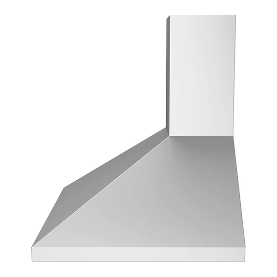
MOUNTING BRACKETS: Upper Chimney Bracket. Lower Chimney Bracket Mounting Bracket Hook... - Page 15 MEASUREMENTS AND DIAGRAMS: The range hood can reach a 9’ ceiling if installed at 31” from cooktop. Height of range hood: 26” - 41 3/8” (66 cm -105 cm)
-
Page 16: Troubleshooting
TROUBLE SHOOTING: 1) If the range hood or halogen light does not • Check if the range hood has been plugged in, operate after installation: make sure that all power has been turned back ON,fused not blown and all electrical wiring are properly connected. -
Page 17: Range Hood Assembly
RANGE HOOD ASSEMBLY: Description... -
Page 18: Specifications
SPECIFICATIONS: Stainless steel Body design 120V / 60Hz (USA & Canada standard) L s Certified Power rating Total input power Motor input power 00 W Total Ampere 3. A 3 levels Levels of speed control Radio frequency interference protected Interference Protection Single motor Number of Motor Single squirrel cage... -
Page 19: Blower Assembly
BLOWER ASSEMBLY: Description eller ELECTRICAL ASSEMBLY: Description Description Electrical box base Screw (ST3*6) Electrical cover Capacitor Screw (ST3*10) - Page 20 USE AND CARE INFORMATION: Operations: • Read and understand all instructions and warnings in this anual before operating the appliance Save these instructions for future reference • Always leave safety grills and filters in place Without these co ponents, operating fans could catch on to hair, fingers and loose clothing •...
Need help?
Do you have a question about the AN-1160 and is the answer not in the manual?
Questions and answers