Table of Contents
Advertisement
Quick Links
Contents
1. Cautions for safety ................................................................................................................................................. 6
1. Before operate the equipment (Safety warning) ................................................................................ 7
2. Before handle cables (Safety instruction) ............................................................................................... 8
3. Before handle the vibrator and water temperature sensor ......................................................... 8
4. Precautions ........................................................................................................................................................ 9
2. Specifications ............................................................................................................................................................ 10
1. Tx, Rx Specifications .................................................................................................................................... 11
2. Specification of display unit ....................................................................................................................... 11
3. Display functions .......................................................................................................................................... 12
4. Component ..................................................................................................................................................... 13
3. Discription .................................................................................................................................................................. 14
1. Display discription ........................................................................................................................................ 15
2. Power ON/OFF ................................................................................................................................................. 16
3. Menu .................................................................................................................................................................... 17
4. Display mode ................................................................................................................................................. 19
4. Functions ................................................................................................................................................................... 20
1. SONAR ................................................................................................................................................................ 21
1.1 Tx Power ............................................................................................................................................... 21
1.2 Tx Rate ................................................................................................................................................... 21
1.3 Pulse Edge ........................................................................................................................................... 22
1.4 Pulse Length ......................................................................................................................................... 22
1.5 Frequency Setting ............................................................................................................................... 23
1.6 Frequency Adjust ................................................................................................................................ 23
1.7 Tx Fix ......................................................................................................................................................... 24
1.8 Bottom Search ..................................................................................................................................... 24
1.9 Trigger Sweep ....................................................................................................................................... 25
2. Display ................................................................................................................................................................. 26
2.1 Mode ..................................................................................................................................................... 26
2.2 Range ..................................................................................................................................................... 26
2.3 Auto Range ......................................................................................................................................... 27
2.4 Display Speed .................................................................................................................................... 27
2.5 Interference/Noise Reduction ..................................................................................................... 28
1
2
Advertisement
Table of Contents
Troubleshooting

Related Manuals for Samyung SDF-315


Summary of Contents for Samyung SDF-315
-
Page 1: Table Of Contents
Contents 1. Cautions for safety ..............................6 1. Before operate the equipment (Safety warning) ................7 2. Before handle cables (Safety instruction) ....................8 3. Before handle the vibrator and water temperature sensor ............8 4. Precautions ................................ 9 2. Specifications ................................10 1. - Page 2 2.6 Refresh Area ............................28 4.15 Lati./Longi ............................44 2.7 TVG ................................29 2.7.1 TVG level setting ......................29 5. Alarm ................................. 44 2.7.2 TVG distance setting ...................... 29 5.1 Alarm ..............................44 2.8 STC ................................30 2.9 Gain Offset ............................30 2.10 Auto Gain Offset ..........................
-
Page 3: Cautions For Safety
10. Calibration ............................... 54 10.1 Temperature ............................. 54 10.2 Voltage ............................... 54 10.3 Beam Angle ............................54 5. Connecting other devices ..........................55 1. Installation ................................. 56 2. Cable connection............................57 3. Rear Connector Pinout ..........................58 Cautions for safety 4. -
Page 4: Before Operate The Equipment (Safety Warning)
1. Before operate the equipment (Safety warning) 2. Before handle cables (Safety instruction) Caution Caution Hazardous voltage exists inside the equipment. Use the regular power code to prevent heating and fire. Do not disassemble or reorganize this equipment except of approved technician. ... -
Page 5: Precautions
4. Precautions 1. Turn the power off when start engine. Rapid change of battery voltage is occurred when start engine and it cause bad effect to equipment. 2. Power supply: 12-35VDC This equipment should be used in range of power 12~35VDC. Specification 3. -
Page 6: Specification Of Display Unit
3. Functional specification 1. TX/RX specification TX frequency and output Frequency : Select two among 28/38/50/55/68/75/82/88/95/100/107/150/200KHz Display TX output : 1 / 2 / 3KW , Transmit by turns Display color : 8 / 16 / 64 , ... -
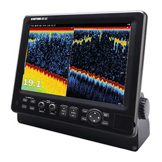
Page 7: Component
DATA connector SCN-16-7P Transducer SCK-25-8P When connect with own connector transducer of vessel Installation 1SET accessory Operation manual Easy manual This chapter explains about SDF-315 equipment and display. Display description Power ON/OFF Menu tree Screen mode... -
Page 8: Display Discription
Capture displayed screen. Save Access saved captured image. Access 2 Power ON/OFF Power ON Press the button. About 2 seconds later, Samyung company logo is displayed and fish finder is available. Power OFF Press and hold button for 5 seconds. -
Page 9: Display Mode
5.ALARM 1. Depth 6.ETC 1. Language 3 Menu tree 2. Temp. 2. Key Beep 3. Fish 3. Func Key 1. Mode 1.SONAR 1. Tx Power 2.DISPLAY 4. Push Button 2. Range 2. Tx Rate 5. Simulation 3. Auto Range 3. Pulse Edge(L) 6. - Page 10 The fish finder provide unique display mode for each mode. Press Screen button to select a desired screen mode. Screen mode switch Functions This chapter explains the functions of SDF-315 High Frequency Low +high frequency Low Frequency Sonar ...
- Page 11 1. Sonar 1.3 High resolution pulse 1.1 Transmitting (Tx)Power If you set it ON then, you can reduce your interference on other vessel. If same frequency is used by near vessel s fish finder, Setting for low frequency pulse edge there could be interference noise in the display.
-
Page 12: Frequency Setting
1.5 Frequency setting 1.7 Fixed Transmission (Tx Fix) Select a frequency to be displayed in high and low frequency screen. Below is the transmission/receiving fixed type according to transducers. - Low frequency: transmit and receive low frequency & high frequency in order using the low frequency transmitter. - High frequency: transmit and receive low frequency &... -
Page 13: Trigger Sweep
1.9 Trigger Sweep 2. Display This can reduce electrical interference noise of other vessel by transiting signal irregularly 2.1 Mode It can set a screen display mode. Setting for Trigger Sweep [MENU] Select [Sonar] Select [Trigger Sweep] (Select ON/OFF) ... -
Page 14: Auto Range
2.3 Auto Range 2.5 Interference Range can be adjusted manually or automatically. Their induced noise from the electric apparatus and the occurrence of periodic interference Automatic adjustment useful when from the lineup of a fish finder is the ability to eliminate noise. preoccupied with other tasks and do not have the time to adjust the display. - Page 15 2.7 TVG 2.8 STC A fish school at a deep depth is displayed in weak colors even if it is equal in strength to one This is useful to clear the surface of unwanted echoes to look for surface fish. The setting in shallow waters.
- Page 16 3. Color 2.10 Automatic gain offset 3.1 day/night In automatic operation, seabed is automatically adjusted as reddish-brown color. You can It can change the menu and background color of the screen. When you select day, the screen modify offset value to set the sensitivity up or down in automatic gain. Clutter function is bright and menu is white.
- Page 17 3.3 hue 3.5 Color erase It can select the hue of pictures according to brightness and taste Needless dim noise can be eliminated by color erase Because this function removes unwanted low level echoes off the screen by cutting them off, ...
- Page 18 3.7 White line 3.9 color of water temperature White line allows you to identify easily between fish school on the bottom and seabed. The Water temperature graph can be modified. strong colors (seabed, big fish school, high density fish school) are displayed as white band, ...
- Page 19 4. View 4.3 A-SCOPE 4.1 display direction A-scope is the picture to show the strength of echo amplitude Select the display direction. on the right side of the screen. As A-scope display big amplitude left : from right to left by big echo and small amplitude by small echo, it allows to right : from left to right identify easily small fish school, sea bottom and geology.
- Page 20 4.5 depth scale 4.7 Color table It can modify depth scale It can select whether it will show the color table on the right in the center of screen or not Setting for depth scale Setting for color table [MENU]...
- Page 21 4.11 Setting for unit 4.9 Detection area Depth : select depth unit temperature : select temperature unit. It can select whether it will show the detection range or not Setting for detection area [MENU] select [view] select [detection area] (Select among on/off) ...
- Page 22 4.13 Date/Time Select displaying GPS dat/time on upper left corner of the screen. (*GPS connection is required) Select displaying date/time [MENU] [displaying] input [date/time]select ( off/on 4.14 COG/SOG Select displaying GPS compass/speed on left upper corner of the screen. (*GPS connection is required) ...
- Page 23 5. Alarm 6. ETC 5.1 Setting for alarm 6.1 Language The Language menu selects the language to use depth : when the depth is out of setting range, alarm alerts you. Setting for language temperature : when the water temperature is out [MENU]...
- Page 24 7. Zoom 6.4 Push Button 7.1 Zoom mode When the push button is off, Sensitivity will not be changed to automatic mode or manual mode regardless the user push the button for sensitivity adjustment. Select your desired zooming mode as belows; ...
- Page 25 8. Fish Schools 8.1 Display of fish schools Display the school of the fish and size. If depth displaying unit is meter then it will be displayed as Cm If depth displaying unit is ft/fa then it will be displayed as inch. ...
- Page 26 9.3 NMEA Input 9. NEMA NMEA input port configuration. 9.1 NEMA Output It will transmit DPT etc (ex water depth).among the standard of NMEA0183 through RS-232C port. It will transmit RS-232C once it is off. Setting for NMEA output ...
- Page 27 9.6 Local offset 9.4 Monitor UART Provided time information from GPS is Both of RS-232c port can be monitored GMT, user can set appropriate time zone. Access UART monitor [MENU]select [NEMA] Select [UART monitor] To return press [MENU] ...
-
Page 28: Temperature
Bean angle is frequency angle from transducer. Low frequency can detect wide area and higher frequency can detect lower area. Bean angle can be modified from 4˚ to 26˚ This chapter will explain the maintenance and defectiveness of SDF-315 Depending on beam angle, receiving radius of bottom can be displayed on A-Scope and receiving radius can be changed depending on type of beam angle. -
Page 29: Installation
2. Cable connection 1. Installation Connect power supply and transducer to the proper connector. Installation of display bracket 1 Locate the bracket mounting on a proper location. 2 Hold the display unit and fix it with bolts 3 Insert bracket mounting bolts gently. Separate display from bracket. -
Page 30: Rear Connector Pinout
3. Rear connector pinout . Connecting power cable Pin position at the back of the transmission indicator. POWER connector on the back of the display is connected to the power cable. NAME1/ALARM ETHER NET ① RD- ② RD+ ① GND ③... -
Page 31: Maintenance And Troubleshooting
Do not use solvents such as thinner, acetone or benzene to clean the unit. They can remove paint and marking. This section describe the maintenance and trouble-shooting of SDF-315. System maintenance and repair Trouble-shooting... -
Page 32: Troubleshooting
Display is night mode Screen flicker or white lines Contact of LCD connector This section describe the appendix related to the equipment operation of SDF-315 Change of screen color Cleanness around LCD connector Product outline drawing Fish school isn’t display on...
Need help?
Do you have a question about the SDF-315 and is the answer not in the manual?
Questions and answers