Table of Contents
Advertisement
Quick Links
Issue 5
June 2019
VF04
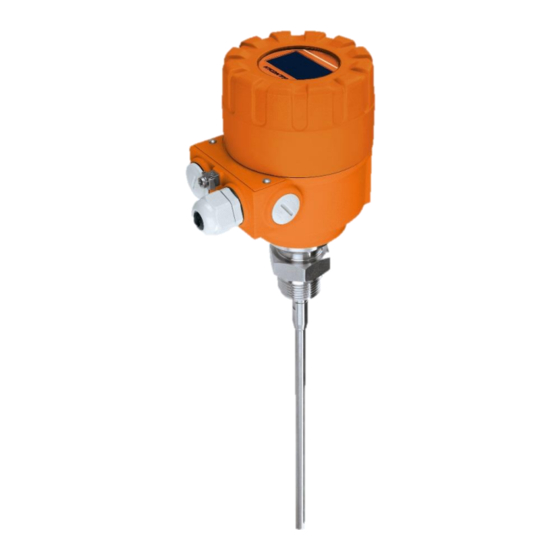
VF04 2-WIRE GUIDED (TDR)
LEVEL TRANSMITTERS
USER AND PROGRAMMING MANUAL
Hycontrol Ltd, Larchwood House, Orchard Street,
Redditch, Worcestershire, UK. B98 7DP
Tel: +44 (0)1527 406800 Fax: +44 (0) 1527 406810
Email: sales@hycontrol.com Web: www.hycontrol.com
Company registered in England No: 1755684
Advertisement
Table of Contents

Subscribe to Our Youtube Channel
Related Manuals for Hycontrol VF04


Summary of Contents for Hycontrol VF04
- Page 1 VF04 VF04 2-WIRE GUIDED (TDR) LEVEL TRANSMITTERS USER AND PROGRAMMING MANUAL Hycontrol Ltd, Larchwood House, Orchard Street, Redditch, Worcestershire, UK. B98 7DP Tel: +44 (0)1527 406800 Fax: +44 (0) 1527 406810 Email: sales@hycontrol.com Web: www.hycontrol.com Company registered in England No: 1755684...
- Page 2 GUIDED MICROWAVE LEVEL MEASUREMENT 2 / 51...
-
Page 3: Table Of Contents
Summary of Parameter functions In HyView 5.1.3 Configuration: configuration examples Programming with VGF-DISPLAY display unit 5.2.1 VGF-DISPLAY display unit 5.2.2 VF04’s behaviour in manual programming mode 5.2.3 Manual programming requires a VGF-DISPLAY module Programming with HART handheld (HHC) Communicator ® 5.3.1... -
Page 4: Introduction
Operating principle The VF04 2-wire guided microwave level transmitter uses the TDR (Time Domain Reflectometry) principle. The instrument sends low power nanosecond wide pulses along an electrically conductive rod, cable or coaxial probe with a known propagation speed (the speed of light). As the pulse reaches the surface of the medium or ... -
Page 5: Order Code
2. ORDER CODE VF04 * 2-wire guided microwave level transmitter NSERTION NSERTION ROBE CONN OUSING UTPUT LENGTH LENGTH Transmitter Coaxial / 1” BSP Aluminium Coaxial, Rod, Coaxial, Rod, 4 – 20 mA + HART / Normal Coaxial / 1” NPT... -
Page 6: Atex, Explosion Protection, Ex Markings, Ex Limit Data
X MARKINGS X LIMIT DATA PECIAL DATA FOR X CERTIFIED MODELS LUMINIUM HOUSING VF04-4-5Ex,6Ex,8Ex II 1 G Ex ia IIC T6…T3 Ga, II 1 G Ex ia IIB T6…T3 Ga Ex marking (ATEX)* II 1 D Ex ia IIIC T85°C…T180°C Da, II 1/2 D Ex ta/tb IIICT85°C…... - Page 7 VF04A-- VF04T-- VF04D-- VF04B-- VF04U-- VF04E-- VF04C-- VF04H-- 4mm twin cable Twin rod Coaxial Denomination Max. measuring 24 m distance Min. measuring distance 0.15 m / 0.3 m 0.15 m / 0.3 m r = 80 / r = 2.4 Min.
- Page 8 ECHNICAL DATA OF THE COATED PROBES VF04F-- VF04TX-- VF04TY-- VF04TM-- VF04TQ-- VF04TI-- VF04G-- 4mm FEP coated 4mm FEP coated 4mm FEP coated 4mm fully FEP Denomination Fully PFA coated rod Fully PP coated rod cable cable cable coated cable Max. measuring distance...
- Page 9 VF04TF-- VF04TX-- VF04TY-- VF04TM-- VF04TQ-- VF04TI-- VF04TG-- Housing Cable gland High temp. connection Mono cable probe Weight Twin cable probe Twin cable separator Twin rod separator Twin rod probe Mono rod probe Grounding screw Process connection Coaxial probe 9 / 51...
-
Page 10: Accessories
3.5 M AINTENANCE AND REPAIR VF04 does not require maintenance on a regular basis. In some very rare instances, however, the probe may need cleaning to remove deposited material. This must be carried out gently, without damaging the probe. Repairs during or after the warranty period are carried out exclusively at the Manufacturer. The equipment sent back for repair should be cleaned or disinfected by the User. -
Page 11: Mechanical Installation
4. MECHANICAL INSTALLATION 4.1 H ANDLING AND STORAGE The device will weigh between approximately 3 kg or 7 lb and 12 kg or 25 lb. Carry the device carefully by the converter housing using both hands. If necessary, use lifting gear. No attempt should be made to lift the instrument by its probe. -
Page 12: Mounting On The Tank
Threaded process connections Nozzle height The simplest and most economical way is to mount the VF04 2-wire directly Do not fit a nozzle longer than its diameter, especially for single on the tank with the 1” (1½”) BSP or 1” (1½”) NPT threaded connection. - Page 13 or use a Process connection and entry pipe Install far from deflector entry pipe plate Caution: Do not put the nozzle close to the entry pipe. medium Pouring the product directly onto the probe will give false readings. Install deflector plate if impossible to distance instrument from entry pipe.
- Page 14 Agitator in the tank 1 Agitator 2 Support beam perpendicular to the pulse direction 3 Abrupt changes in tank cross section 4 Heating tubes 5 Alternative solution: reference chamber - electromagnetic field is within chamber 6 Instrument’s electromagnetic field : Any intruding metallic object will be detected in this zone if perpendicular to the emitted pulse direction.
-
Page 15: Specific Installation Instructions: Instrument - Solid Applications
4.2.2 S PECIFIC INSTALLATION INSTRUCTIONS INSTRUMENT SOLID APPLICATIONS ALSE READINGS Do not let the probe touch the side of the nozzle Conical silo nozzles, false readings and traction on the cable probes 2 High traction forces: We recommend that the probe should not be anchored to avoid excessive traction loads on the cable. -
Page 16: Wiring
Electrostatic discharge (E.S.D.) VF04 2-wire non-Ex and Ex instrument electronics are shielded up to 4 kV against E.S.D. Note: E.S.D. cannot be fully solved by the VF04 2-wire internal E.S.D. protection. It is the customer’s responsibility to avoid E.S.D. by grounding the tank, product and probe installation. - Page 17 20 mA Loop current, mA Line A = minimum voltage at the VF04 2-wire terminals Line B = minimum supply voltage (for voltage drop caused by a 250 Ohm loop resistance) Example for calculating the power supply: The voltage drop is tested at 22 mA:...
- Page 18 For calculation of the supply voltage the same applies as for the standard non-’Ex’ version. Ex area area VF04 2-wire The connected Ex repeater must be HART®-compatible so that it can be operated with the HyView communication software or the [Ex ia] 4-20mA HART®...
-
Page 19: Bus
’Ex ia’ current output and HART® - Intrinsically safe passive, HART® protocol In accordance with the Rosemount Standard, HART® communication can be used with a VF04 2-wire. It is used as a point-to-point connection between the VF04 2-wire as slave and the HART® master. N x 4 mA + HART 4…20 mA + HART... -
Page 20: Programming
5. PROGRAMMING VF04 can be programmed in three (basic) ways. Programming with HyView software Programming with VGF-DISPLAY display unit Programming with HART® Handheld (HHC) Communicator (For operating instruction see the User manual of the HHC) 5.1 P... - Page 21 Add Network Click “Network” from the menu then click the Add Network button. Choose the communication port. Click the Ok button Click the Detect button to start the device selection on the selected communication port. 21 / 51...
- Page 22 The above Scanning network window appears when the detection starts To select the detected devices tick the checkbox and click Device settings button. Parameter reading is in progress Device has been detected and settings are being read. 22 / 51...
- Page 23 Settings have been read. 23 / 51...
-
Page 24: Summary Of Parameter Functions In Hyview
5.1.2 UMMARY OF ARAMETER FUNCTIONS The table below provides an overview of all parameters that can be set in the Device Identification Menu. Default values are in bold type in the “Input Range” column. 5.1.2.1 DEVICE IDENTIFICATION Function Input Range Description 1.6.0 Serial I/O For integrating into a HART®... - Page 25 5.1.2.2 APPLICATION SETTINGS Function Input Range Description 1.2.0 Display Options 1.2.4 Calculation system Select Metric (EU), Imperial (US) or Determines what length units are presented in 1.2.4. Optional Unit 1.2.5 Length unit If Metric(EU) selected Length unit of displayed value (level / distance). Select m, cm, mm, The optional unit allows the user to define a new unit (name and factor) see menu 1.2.6.1...
- Page 26 5.1.2.3 MEASUREMENT CONFIGURATION SETTINGS Function Input Range Description 1.0.0 Operation 1.1.0 Basic parameters 1.1.1 Tank height Enter 0 … 60 000 mm or The tank height is defined as the distance between the bottom of the tank and the lower 0 …...
- Page 27 5.1.2.4 OUTPUT SETTINGS Function Input Range Description 1.3.0 Outputs 1.3.1 Current generator Select Off, Level, Distance, Volume* or Current output function (measured value to be displayed). mode Ullage volume* (Current I1 item) Level 1.3.5 Error indication Select This parameter defines the status the current output assumes in the event of a fault: (Current range) Hold –...
- Page 28 5.1.2.5 MEASUREMENT OPTIMIZATION SETTINGS Function Input Range Description 1.1.3 Damping Time 1 … 100 s. The time constant allows filtering of possible signal fluctuations when the product surface is constant turbulent. 5.1.2.6 VOLUME LINEARIZATION SETTINGS 28 / 51...
-
Page 29: Configuration Configuration Examples
1.7.0 Volume table For calibrating the instrument for volume measurement. 1.7.2. Input table Select point 01 to 20, enter level and then This function is used for setting up the strapping table (level/volume). Up to 20 points volume values respectively. can be assigned. - Page 30 The top dead zone is the minimum measuring distance between the instrument flange facing (the reference point) and the product. The various probes for the VF04 2-wire have differing top dead zones and these are given in section 3.2: Technical data of the probes – Min.
- Page 31 Level reflection outside dead zone 8600mm 8850mm(3) level/mm Level reflection inside dead zone 8850mm 8850mm(3) level/mm No level reflection inside detection delay zone 8850mm 8850mm(3) level/mm Height of tank fitting Detection delay (Function1.5.1=120 mm) Dead zone limit (Function1.1.2=150 mm) Emitted signal Flange reflection (masked) Masked zone (all signals here are ignored) Level reflection outside dead zone –...
- Page 32 Note: The level can effectively be measured between 200 mm or 8” and 5600 mm or 18½ ft. When the product level drops below the tip of the probe, the VF04 2-wire will indicate that there still remains 200 mm or 8”. Accordingly, the VF04 2-wire can only indicate a level between 200 mm or 8” and 5600 mm or 18½ ft, since it only measures along the probes.
- Page 33 Enter first set of values and click ok. Reselect ‘Add new item’ and enter second value. Repeat adding values until all values are entered. After table is complete press the send button to transfer the information to the instrument. 33 / 51...
- Page 34 Go to user function 1.3.3 “Scale I1 max” to enter volume value for the maximum output (20 mA) 16.80 m³ Save the new configuration to disk by clicking on ‘Save to disk’ and download it onto the VF04 2-wire using the ‘Send to’ button.
-
Page 35: Programming With Vgf-Display Display Unit
ROGRAMMING WITH DISPLAY UNIT The main parameters of the VF04 can be also set using the VGF-DISPLAY display unit. The default display shows the primary measured value (which the output current is calculated from). Besides the numerical display there is a bargraph on the right showing the value of the current output. -
Page 36: Vf04'S Behaviour In Manual Programming Mode
If HART communication stops the COM LED turns off after 120 sec. When leaving the VF04 in (programming) menu after 30 minutes the instrument automatically returns to measuring mode. If VGF-DISPLAY is removed the instrument instantly returns to measuring mode. -
Page 37: Programming With Hart ® Handheld (Hhc) Communicator
5.3 P HART (HHC) C ® ROGRAMMING WITH HANDHELD OMMUNICATOR Display and configuration can also be carried out with a HART® communicator... Communicator layout Two-pin jack for loop connectors Function keys (F1 … F4) Action keys On/off Arrow LEFT DOWN RIGHT Arrow Arrow... - Page 38 Configuration: summary of user functions via HART® Communicator HC 275 (Version 1.00) Reset default values are in bold type in the “Input Range” column. Refer to the HART® HC275 Communicator operating instructions for further operating details. Function Input Range Description PROCESS VAR.
- Page 39 Select 4-20 mA or 4-20 mA + 22 mA if error Current output range 4 … 20 mA (1 choice). When the VF04 2-wire is in error mode, the current output is frozen except if the second choice is 4 - 20 mA selected and then the current output is fixed at 22 mA.
- Page 40 DISTANCE INPUT Enter a value from Function This function forces the VF04 2-wire to search for the product surface in a zone 2.1.1.4: Dead zone to Function other than the actual measuring zone. If there is no level signal, you can enter 2.1.1.2: Probe length...
-
Page 41: Characters Available For Alpha-Numerical Data Functions In Hyview And On The Hart ® Console
DATE Month Day Year (xx / xx / xx). 5.10 NUM RESP PREAM Number of preamble in the response frame of the device 5.11 Tag name of the VF04 2-wire 5.12 POLL ADDRESS Address of the device. 5.3.1 HART ®... -
Page 42: Instrument Operating Logic When The Reflection Is Lost
The configurations described below are illustrated in the previous diagram The “current output” range is smaller than the max. possible measuring range The “current output” range is equal to the measuring range: Scale min.: 4 mA (Function 1.3.3) = tank height – probe length + H Scale max.: 20 mA (Function 1.3.4) = tank height –... -
Page 43: Gain And Voltage Amplitude
Level measurement: Level pulse amplitude and threshold After connection to a power supply, the VF04 2-wire will: 1. Measure reflection pulses in terms of voltage amplitude by cycling through a set of gains. 2. Identify the highest amplitude as being the product level. - Page 44 The level signal can be optimized by way of two factors: Amplification factor The amplitude of the signals is proportional to the dielectric constant of the product. At low amplitudes the signal should be amplified. The amplification factor is dependent on the dielectric constant and on the probe type.
-
Page 45: Typical Signal Trends
5.4.3 YPICAL SIGNAL TRENDS The following diagrams show characteristic signals that have been recorded with the oscilloscope function. Emitted pulse Emitted pulse Level signal Flange Flange Level signal Rod or cable probe with gain 1 Rod or cable probe with gain 2 Emitted pulse Emitted pulse Level signal... -
Page 46: Automatic Adjustment
In the event of operational or installation faults, you can frequently identify the cause of the fault by means of this function and normally eliminate it yourself. Should the fault persist, please send a copy of the screen shots to your HYCONTROL Service Centre. -
Page 47: Level Measurement When More Than One Phase Or Layer In The Tank
/ V With Factory Menu Function 1.1.3: Application Type set to 1 liquid, 1 level, the VF04 2-wire will search for the return signal with the highest amplitude (i.e. higher than the threshold). It will measure the oil level. -
Page 48: Troubleshooting
The VF04 2-wire indicates an The VF04 2-wire measures a non-valid reflection. Check the tank for obstructions and verify that the probe is clean. incorrect level value. In the case the indicated level is close to the nozzle, increase the detection delay and the dead zone with the same ratio or increase the threshold level if the full measurement range is essential. - Page 49 Check the current loop and the connections. does not correspond to the Configure the output as described in Sect. 3.3.3 (user sub-menu 1.3) of the VF04 value at the display 2-wire Handbook – also try adjusting the threshold in the Measurement (HyView or optimization screen (HyView) or menu 2.1.5.1.0 HART®...
-
Page 50: Appendix 1. Atex Safety Guidelines
APPENDIX 1. ATEX SAFETY GUIDELINES ATEX Safety guidelines for the use of the VF04 2-wire Non-contact guided level transmitter General: Instruments with the code according to ATEX directive 2014/34/EU VF04-4-5Ex, VF04-4-6Ex or VF04-4-8Ex are designated as ATEX instruments See Ex markings and Maximum surface temperature data for group, category and temperature classification data. - Page 51 June 2019 Hycontrol reserves the right to change technical data without notice! 51 / 51...
Need help?
Do you have a question about the VF04 and is the answer not in the manual?
Questions and answers