Subscribe to Our Youtube Channel
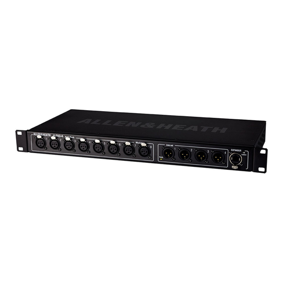
Summary of Contents for ALLEN & HEATH AR84
- Page 1 ALLEN&HEATH Service manual AR84 AR2412 Copyright © 2012 Allen & Heath Limited. All rights reserved Allen & Heath Limited Kernick Industrial Estate, Penryn, Cornwall, TR10 9LU, UK ALLEN&HEATH AR84 AR2412 service manual_1...
- Page 2 Contents 3 Warranty 4 Precau ons 5 Tes ng and part iden fica on 6 AR84 Service access 7 AR84 Remove comms PCB 11 AR84 Re‐assemble 13 AR2412 Service access 15 AR2412 Remove comms PCB 18 AR2412 Re‐assembly 19 AR2412 Ready LED ALLEN&HEATH AR84 AR2412 service manual_1...
-
Page 3: Limited One Year Warranty
Units returned should be packed to avoid transit damage. In certain territories the terms may vary. Check with your ALLEN & HEATH agent for any additional warranty which may apply. For further assistance please contact our distributor or your territory. ALLEN&HEATH AR84 AR2412 service manual_1... - Page 4 Remove any dirt or debris as this may cause equipment failure in the future. Ensure all assemblies, harnesses and connectors are correctly aligned and plugged in. Ensure that jumper settings and control configurations are correctly set according to the requirements of the customer. Continued - ALLEN&HEATH AR84 AR2412 service manual_1...
- Page 5 Allen & Heath do not publish schematics that contain digital audio and control circuitry. Parts Identification A Parts Identification document is published separately on the Technical Re- sources tab available when logged in as a distributor. ALLEN&HEATH AR84 AR2412 service manual_1...
- Page 6 Remove cover screws Remove cover ALLEN&HEATH AR84 AR2412 service manual_1...
- Page 7 Remove RJ45 clip Protect paint ALLEN&HEATH AR84 AR2412 service manual_1...
- Page 8 Remove PCB screw Remove RJ45 screws ALLEN&HEATH AR84 AR2412 service manual_1...
- Page 9 Remove iDR Rack Comms PCB ALLEN&HEATH AR84 AR2412 service manual_1...
- Page 10 Cable e Disconnect connector ALLEN&HEATH AR84 AR2412 service manual_1...
- Page 11 Re‐assemble Place cable e over moun ng pillar Line up LED ALLEN&HEATH AR84 AR2412 service manual_1...
- Page 12 ALLEN&HEATH AR84 AR2412 service manual_1...
- Page 13 ALLEN&HEATH AR84 AR2412 service manual_1...
- Page 14 Disconnect DC harness ALLEN&HEATH AR84 AR2412 service manual_1...
- Page 15 Remove RJ45 clips x3 ALLEN&HEATH AR84 AR2412 service manual_1...
- Page 16 Remove RJ45 screws Remove PCB screws ALLEN&HEATH AR84 AR2412 service manual_1...
- Page 17 ALLEN&HEATH AR84 AR2412 service manual_1...
- Page 18 ALLEN&HEATH AR84 AR2412 service manual_1...
- Page 19 The Ready LED is fi ed to all I/O PCBs. It is not used on O/P 1 & 5 and is bent up, inside the chassis. ALLEN&HEATH AR84 AR2412 service manual_1...


Need help?
Do you have a question about the AR84 and is the answer not in the manual?
Questions and answers