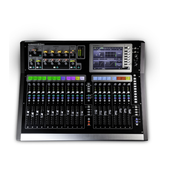
Summary of Contents for ALLEN & HEATH GLD-080
- Page 1 DISTRIBUTION ALLEN&HEATH Service manual GLD-080 Copyright © 2012 Allen & Heath Limited. All rights reserved Allen & Heath Limited Kernick Industrial Estate, Penryn, Cornwall, TR10 9LU, UK ALLEN&HEATH GLD-080 service manual _1_1...
- Page 2 16 004‐182 Bank R 13 Harness and connec ons 16 004‐178 12 Fader master 13 Internal DC flow 16 004‐179 8 Fader slave 14 004‐282 PSU 17 004‐191 SBC 14 004‐184 Audio/Power 15 004‐173 DSP 15 004‐288 Mini Backplane 15 004‐186 Fan controller 15 004‐191 SBC 15 004‐276 Processing 16 AE8562 Touch screen 16 004‐180 TFT Right 16 004‐183 Headphone PCB 16 004‐ 12 channel LCD ALLEN&HEATH GLD-080 service manual _1_1...
- Page 3 For further assistance please contact our distributor or your territory. Parts Iden fica on or full parts iden fica on, refer to the GLD‐080 Parts Iden fica on document available via the Technical Resources tab on the distributor log‐in web pages. Diagnos cs Allen & Heath do not publish schema cs that contain digital audio and control circuitry. Repair of the GLD system is by diagnosing which PCB or harness is faulty and replacing the part. The GLD SBC manages all data flow and control, via USB. Audio IN/OUT to and from the DSP and internal DC supplies are carried between PCBs by flat harnesses. With power OFF : Disconnec ng USB connec ons and flat harnesses may help the engineer to diagnose which harness or PCB is faulty. ALLEN&HEATH GLD-080 service manual _1_1...
- Page 4 Remove any dirt or debris as this may cause equipment failure in the future. Ensure all assemblies, harnesses and connectors are correctly aligned and plugged in. Ensure that jumper settings and control configurations are correctly set according to the requirements of the customer. Continued - ALLEN&HEATH GLD-080 service manual _1_1...
- Page 5 Allen & Heath do not publish schematics that contain digital audio and control circuitry. Parts Identification A Parts Identification document is published separately on the Technical Re- sources tab available when logged in as a distributor. ALLEN&HEATH GLD-080 service manual _1_1...
- Page 6 Remove base screws Remove base panel ALLEN&HEATH GLD-080 service manual _1_1...
- Page 7 8 ch LCD 12 ch LCD AE8430 AE8429 004-176 004-177 12 channel 8 channel 004-178 004-179 fader master fader slave 004-182 Bank Right 2 004-181 Bank Mid 1 ALLEN&HEATH GLD-080 service manual _1_1...
- Page 8 Remove rear screws Remove lower screws ALLEN&HEATH GLD-080 service manual _1_1...
- Page 9 Li rear sec on Disconnect cable ALLEN&HEATH GLD-080 service manual _1_1...
- Page 10 Lay base on chasis SBC 004‐191 004-276 Processor 004-288 DSP 004-186 Fan Controller mini backplane I/P O/P 004-173 PSU 004‐282 004-184 Audio / Power ALLEN&HEATH GLD-080 service manual _1_1...
- Page 11 Use a heat source to warm the overlay. Push the centre of the screen. ALLEN&HEATH GLD-080 service manual _1_1...
- Page 12 Support the rear of the screen. Remove screen. ALLEN&HEATH GLD-080 service manual _1_1...
- Page 13 Detail on following pages ALLEN&HEATH GLD-080 service manual _1_1...
- Page 14 See p.13 for large view ALLEN&HEATH GLD-080 service manual _1_1...
- Page 15 See p.13 for large view ALLEN&HEATH GLD-080 service manual _1_1...
- Page 16 See p.13 for large view ALLEN&HEATH GLD-080 service manual _1_1...
- Page 17 See p.13 for large view ALLEN&HEATH GLD-080 service manual _1_1...


Need help?
Do you have a question about the GLD-080 and is the answer not in the manual?
Questions and answers