
Subscribe to Our Youtube Channel
Related Manuals for ALLEN & HEATH GL4000


Summary of Contents for ALLEN & HEATH GL4000
- Page 1 PSU not included in public version. Please see distributor version. ALLEN&HEATH GL4000 Dual Function Audio Mixing Console SERVICE MANUAL PUBLICATION: AP2640...
-
Page 2: Safety Warning
The information presented in this manual is intended for competent technical personnel to carry out service and product support for the GL4000. It is assumed that the reader is familiar with the related electronic theory and audio terminology, and is able to carry out basic servicing, fault-finding and repair of audio equipment of this type. Service personnel should also be familiar with audio systems, mains earthing and power requirements, as well as handling precautions. -
Page 3: Table Of Contents
CONTENTS SECTION A TECHNICAL DESCRIPTION .................... 2 STANDARD CONSOLE FORMATS & OPTIONS ............. 3 GL4000 DIMENSIONS FOR FLIGHTCASING ..............4 GL4000M DIMENSIONS FOR FLIGHTCASING ............... 5 SPECIFICATION ......................6 CONNECTIONS ......................7 REMOVING A CHANNEL, GROUP, L/R, MONO or MASTER CIRCUIT BOARD ..... 8 REMOVING THE MICRO CIRCUIT BOARD .............. - Page 4 MPU 3 DIGIT METER CIRCUIT DIAGRAM ..............C2624 SLAVE PCB COMPONENT IDENT ................. AG2628 SLAVE CIRCUIT DIAGRAM .................... C2628 GL4000 METER PCB COMPONENT IDENT ..............AG2092 GL4000 METER CIRCUIT DIAGRAM ................C2092 GL4000M METER PCB COMPONENT IDENT ..............AG3601 GL4000M METER CIRCUIT DIAGRAM ................C3601 SYS-LINK PCB COMPONENT IDENT ................
-
Page 5: Section A
SECTION A SERVICE PROCEDURES CAUTION ! TO AVOID DAMAGE TO INTERNAL COMPONENTS BY MISHANDLING AND/OR MISCONNECTION, ONLY TECHNICALLY COMPETENT PERSONNEL SHOULD ATTEMPT SERVICE WORK ON THIS CONSOLE. Section A - 1 L4DSM2 ALLEN & HEATH... -
Page 6: Technical Description
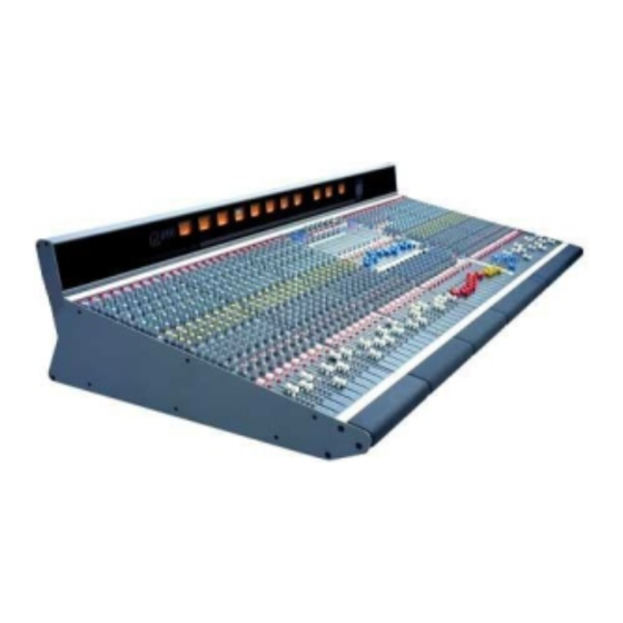
TECHNICAL DESCRIPTION The ALLEN & HEATH GL4000 is an 8 bus Front-of-House and 10 bus On-stage Monitor mixer. It can also be configured for full 8 track, stereo and mono recording. Standard formats are 24, 32, 40 and 48 channels with optional SYS-LINK expander system and RPSD-2 dual supply combiner / monitor. -
Page 7: Standard Console Formats & Options
STANDARD CONSOLES All consoles supplied with separate RPS11 rack mount power unit. Optional RPSD dual supply combiner / monitor. Optional VU meterpod and optional SYS-LINK expander system. GL4000-824S GL4000M-824n M24 VU METERBRIDGE CHANS CHANS CHANS MASTER 9-16 17-24 GL4000-832S GL4000M-832n... -
Page 8: Gl4000 Dimensions For Flightcasing
64.7 115.2 367.6 The RPS11 is supplied with a 2m mains lead with a moulded mains plug and IEC socket. A3m DC output cable is also supplied to connect the RPS11 to the GL4000. MECHANICAL DETAILS PACKED Width Depth Height... -
Page 9: Gl4000M Dimensions For Flightcasing
64.7 115.2 367.6 The RPS11 is supplied with a 2m mains lead with a moulded mains plug and IEC socket. A3m DC output cable is also supplied to connect the RPS11 to the GL4000. MECHANICAL DETAILS UNPACKED Width Depth Height... -
Page 10: Specification
SPECIFICATIONS 0dBu = 0.775 Vrms Reference for high level equipment +4dBu = 1.23 V 0dBV = 1 Vrms Reference for low level equipment -10dBV = 310 mV 0VU meter reading = +4dBu at XLR outputs Input Gain Mic/Line Input ..........+6dB to +60dB variable Mic/Line + Pad .......... -
Page 11: Connections
HEADPHONES OUT ..1/4" JACK ....tip L, ring R ....for stereo headphones 8 to 400 ohms ( 2 SOCKETS) ....1/4" JACK ....tip L, ring R ....for stereo headphones 8 to 400 ohms GL4000 REAR PANEL CONNECTORS Section A - 7 L4DSM2 ALLEN &... -
Page 12: Removing A Channel, Group, L/R, Mono Or Master Circuit Board
To refit the circuit assembly follow the above procedure in reverse order. Make sure all harnesses are correctly aligned and plugged on. Test for correct operation. CONSOLE REAR SLAVE PCB CONSOLE FRONT GL4000-824 inverted with the base cover removed. Section A - 8 ALLEN & HEATH L4DSM2... -
Page 13: Removing The Micro Circuit Board
Make sure all harnesses are correctly aligned and plugged on. Test for correct operation. rear panel view MICRO PCB CONSOLE REAR CONSOLE FRONT GL4000-824 inverted with the base cover removed. Section A - 9 L4DSM2 ALLEN & HEATH... -
Page 14: Removing A Connector Circuit Board
INPUT CONNECTOR CIRCUIT BOARD CIRCUIT BOARD CIRCUIT BOARD CIRCUIT BOARD ASSEMBLY ASSEMBLY ASSEMBLY ASSEMBLY CONSOLE FRONT GL4000-824 inverted with the base cover removed. INPUT SECTION INPUT SECTION MASTER SECTION GL4000 Rear Panel View. Section A - 10 ALLEN & HEATH L4DSM2... -
Page 15: Assigning An Input Connector Board (Channel Mute Assignment)
The diagrams below show the channel mute link assignments for the input connector circuit board assemblies for each console format. Remember when adding an expander to the console the assignment of the links in the console may also require reassigning. Refer to the expander fitting instructions (AP2794). GL4000-824S GL4000M-824n (Stereo configurations differ) stereo... - Page 16 GL4000-832S GL4000M-832n (Stereo configurations differ) stereo 17 - 24 1 - 8 25 - 32 MASTER 9 - 16 GL4000-840S GL4000M-840n (Stereo configurations differ) stereo 25 - 32 1 - 8 9 - 16 MASTER 33 - 40 17 - 24...
-
Page 17: Internal Link Options
INTERNAL LINK OPTIONS The GL4000 is configured to satisfy most of the applications that are likely be encountered. However, the following internal link options are offered for those applications that may require alternative settings. These options require access to the internal circuit assemblies and resoldering of circuit board links. This work should be carried out by technically competent personnel. -
Page 18: Ordering Spare Parts And Assemblies
EPROM version and code number and reason for the replacement. GL4000 software SERVICE TOOLS The tools required to service the GL4000 are standard to an electronics service workshop and are easily obtainable. The following items are necessary for disassembly and service access: 4mm Hexagon (Allen) key (M6 side trim) -
Page 19: Ordering An Assembly
002-164 Slave PCB assembly 002-167 MPU & 3 digit display PCB assembly 002-198 RPS11 PCB assembly 002-047 GL4000 Meterpod PCB assembly LEFT 002-039 GL4000 Meterpod PCB assembly RIGHT 002-040 GL4000M Meterpod PCB assembly LEFT 002-464 GL4000M Meterpod PCB assembly RIGHT... -
Page 20: Ordering A Spares Kit
It is recommended that the spares kit order code 002-177 is held and maintained by the service agent to enable in-field service repairs to the GL4000 independent of the ALLEN & HEATH factory. If you are an existing ALLEN & HEATH service agent who already stocks the spares kit for the ALLEN &... - Page 21 Faders, Potentiometers, switches, and connectors: 10KA fader 100mm Jungpoon* AI2665 10KA x 2 fader 100mm (stereo) Jungpoon* AI2664 10KA fader 100mm Alps K* AI8109 10KA x 2 fader 100mm (stereo) Alps K* AI8110 10KA fader 60mm AI8054 20KK (203K) AI8003 20KB x 2 (203B 14mm wide) AI8006 20KK x 2 (203K 14mm wide)
-
Page 22: Power Supply
POWER SUPPLY: Lamp Neon AL0200 Mains Fuse 20mm T3.15A (UK, EC) AL0464 Mains Fuse 20mm T5A (USA) AL2270 Mains Fuse 20mm T8A (DC) AL0487 Transformer 320VA AM2720 Bridge Rectifier 25A 200V AE0239 Transistor MJ3001 AE0240 Transistor cover (inc. split washers) AK2767 Thyristor TIC126M AE0272... -
Page 23: Section B
SECTION B FITTING INSTRUCTIONS CAUTION ! TO AVOID DAMAGE TO INTERNAL COMPONENTS BY MISHANDLING AND/OR MISCONNECTION, ONLY TECHNICALLY COMPETENT PERSONNEL SHOULD ATTEMPT SERVICE WORK ON THIS CONSOLE. Section B - 1 L4DSM2 ALLEN & HEATH... - Page 24 The expander can be fitted to consoles with the integral meterbridge as well as those consoles that do not have the integral meterbridge. The expander modules allow a GL4000 console to be expanded up to a maximum of 48 channels.
- Page 25 EXPANDER POSITIONING 2. The Expander unit must be fitted in the position shown in the diagrams below. GL4000-824 + Expander 1 - 8 9 - 16 Master 17 - 24 Expander GL4000-832 + Expander 1 - 8 9 - 16...
-
Page 26: Expander Module
INSTALLATION Only technically competent personnel should attempt to fit the expander module. Disconnect the Power Supply Unit and cables from the console before fitting the expander module 3. Ensure you have a good work surface and clear area before starting work. Carefully invert the console and remove the base panel by removing all screws along the edges of the base panel. - Page 27 ‘B’ ‘A’ 5. Attach the adjustable fastener to the inside of the front extrusion of the console and catchplate to the ‘F’ ‘G’ inside of the expander using screws and nuts . The mounting holes are located under the front armrest of each unit and are pre-drilled for the adjustable fastener and catchplate.
- Page 28 ‘H’ 7. Screw the 5 plain studs into the extrusion holes of the expander as shown below. expander ‘B’ ‘A’ 8. Slide the expander module onto the 7 studs and close the adjustable fastener over the catchplate ‘C’ see 5. The fastener can be adjusted to ensure a good join. Screw in the locking screws into the pre- ‘C’...
- Page 29 9. With the expander module and console securely clamped together, bolt the expander and console front ‘D’ ‘K’ panels together using bolts and lock nuts with a 5.5mm spanner. The input channel circuit board assembly nearest the panel flanges will have to be removed to gain access to the fixing holes. 10.
-
Page 30: Master
(AG2622) will have to be assigned to enable the channel mutes to function correctly. For consoles that have the expander on the right hand side of the console (e.g. expanded GL4000-824S and GL4000-840S consoles) only the expander requires assignment. -
Page 31: Gl4000-832 + Expander
GL4000-832 + Expander Note: remove existing assignment links on all connector circuit boards before re-assignment. 1 - 8 9 - 16 Master 17 - 24 25 - 32 Expander 3R 4R 5R 3R 4R 5R 3R 4R 5R 3R 4R 5R... -
Page 32: Master Expander
16. Carefully turn the console the correct way up and fit the new number strips. A complete set of number strips ‘L’ is supplied with the Expander kit. The diagrams below show the combination of strips to be fitted to the expanded consoles. GL4000-824 + Expander 1 - 8 9 - 16 Master... - Page 33 Please note; to prevent damage to the console chassis, the expanded console must be supported along its entire length. Should you experience any difficulties in fitting this module or have any queries regarding your GL4000 console please contact your ALLEN & HEATH agent. Include the console serial number in any correspondence.
-
Page 34: Mixing Console
MIXING CONSOLE SYS-LINK EXPANDER OPTION This option connects a GL4000 console as a channel expander to a second console with just one or two interconnecting cables. Kit GL4000-SL1 = SINGLE Single option to install SYS-LINK to one GL4000 console to allow interconnection to a second console already fitted with SYS-LINK. - Page 35 FITTING THE GL4000 SYS-LINK EXPANDER OPTION CHECK THE CONTENTS : GL4000-SL1 rear extrusion earth wire Ribbon harness assembly supplied pre-formed and connected to circuit board assembly. Rear panel D type chassis connector fixings already fitted. 8 x AB2189 4 x foam strips fig.
- Page 36 Disconnectd the ribbon harness (D) Carefully remove the INPUT CONNECTOR circuit board assembly (A) and place to one side. Now remove the SYS-LINK blanking plate. Chan Chan CONSOLE FRONT GL4000-824 inverted with the base cover removed. fig. 2 ALLEN & HEATH GL4000 SYS-LINK OPTION...
- Page 37 INPUT CHANNEL CIRCUIT BOARD ASSEMBLY GL4000-824 inverted with the input connector circuit board assembly removed. fig. 3 FITTING THE SYS-LINK RIBBON HARNESSES : Place the SYS-LINK circuit board assembly next to the GROUP 1 circuit board with the harness and ribbon cables to the rear of the console.
- Page 38 SYS-LINK ribbon harnesses removed for clarity. SYS-LINK CIRCUIT BOARD ASSEMBLY 8x GROUP CIRCUIT BOARD ASSEMBLY LEFT CIRCUIT BOARD ASSEMBLY RIGHT CIRCUIT BOARD ASSEMBLY MONO CIRCUIT BOARD ASSEMBLY SYS-LINK harness circuit board interconnections fig. 4 ALLEN & HEATH GL4000 SYS-LINK OPTION...
- Page 39 1 aligned with the red stripe of the ribbon harness. REFITTING THE BASE : Refit the base. Turn the console the correct way up and fit the pot nuts and knobs to the INPUT CHANNEL replaced in ALLEN & HEATH GL4000 SYS-LINK OPTION...
- Page 40 The SYS-LINK circuit diagram and technical details are included for reference. The SYS-LINK Applications Note AP2787 is included separately with these fitting instructions. Provide this note to the user as applicable. Please refer any queries to your Allen & Heath appointed service agent. ALLEN & HEATH GL4000 SYS-LINK OPTION...
- Page 41 Connect line level signals of around -2dBu. The GL4000 PFL & AFL systems may be activated by switching the PFL or AFL DC inputs to 0V earth through a 15k ohm resistor.
-
Page 42: Gl4000 Sys-Link Applications Note
IN B GL4000 GL4000 SLAVE MASTER to link GRP 5-8, AUX 7-10, MTX A-D to link GRP 1-4, AUX 1-6, L, R, PFL & AFL MULTI OUT IN A GL4000 SLAVE MASTER GL4000 SYS-LINK APPLICATIONS NOTE AP2787 ALLEN & HEATH... -
Page 43: Meterbridge Fitting Instructions
METERBRIDGE FITTING INSTRUCTIONS PFL/AFL ACTIVE GL4000 meterbridge shown The meterbridge has been designed to compliment the Allen & Heath GL series of Live consoles. Its purpose is to monitor the programme signal at the console main outputs i.e; Groups 1 to 8, Left, Right and Mono. The meterbridge is available in various sizes to fit each console size and runs full length. - Page 44 SECTION C TECHNICAL DIAGRAMS CAUTION ! TO AVOID DAMAGE TO INTERNAL COMPONENTS BY MISHANDLING AND/OR MISCONNECTION, ONLY TECHNICALLY COMPETENT PERSONNEL SHOULD ATTEMPT SERVICE WORK ON THIS CONSOLE. Section C - 1 L4DSM2 ALLEN & HEATH...
- Page 45 In accordance with Allen & Heath’s policy of continual product development, a new fader has been specified for GL4000 consoles. The fader offers a custom taper that has been designed to match the needs of engineers using the consoles in today’s live environment.
-
Page 46: Front Panel Layout
FRONT PANEL LAYOUT Section C - 3 L4DSM2 ALLEN & HEATH... - Page 48 MONO / STEREO INPUT & TALKBACK SHEET 1 OF 3...
- Page 49 GROUP / AUX / MATRIX / LR / MONO / 2 TRACK SHEET 2 OF 3...
- Page 50 MUTE AUTOMATION SHEET 3 OF 3...
- Page 51 GL4000-824 INTERNAL LAYOUT Console inverted with the base removed.
- Page 52 TO MONO PCB (AG2625) CHASSIS EARTH TERMINAL CONSOLE TO MASTER PCB (AG2626) Gn 24/0.2 POWER 2BA SOLDER TAG (AK0001) M5 CRINKLE WASHER (AB0304) WIRING TO LITTLITE XLR'S Refer to LITTLITE wiring diagram TO MPU PCB (AG2624) CHASSIS EARTH TERMINAL DC POWER CONNECTOR GN 24/0.2 Pin 1 = +16V (RED) Pin 3 = -16V (BLACK)
- Page 89 LINK OPT V_DIV_REFA V_DIV_REFA METER VU METER VU METER VU LM393 LM393 LINK OPT METER VU METER VU METER VU 100K 100K 1N4148 1N4148 GRP1/7 TL072 GRP4/L TL072 10/16 10/16 1N4148 1N4148 PR VA 10K PR VA 10K 10/16 10/16 V_DIV_REFA V_DIV_REFA BLGND...
- Page 90 LK11 LK16 LK21 LK26 LINK TCW LINK TCW LINK TCW LINK TCW LINK TCW LINK TCW LK12 LK17 LK22 LK27 LINK TCW LINK TCW LINK TCW LINK TCW LINK TCW LINK TCW LK13 LK18 LK23 LK28 LINK TCW LINK TCW LINK TCW LINK TCW LINK TCW...
- Page 96 SECTION D POWER SUPPLY CAUTION ! TO AVOID DAMAGE TO INTERNAL COMPONENTS BY MISHANDLING AND/OR MISCONNECTION, ONLY TECHNICALLY COMPETENT PERSONNEL SHOULD ATTEMPT SERVICE WORK ON THIS UNIT. Section D - 1 L4DSM2 ALLEN & HEATH...
-
Page 97: Technical Description
AC voltages from the secondary windings of a mains transformer. This unit connects to the local AC mains supply and provides the regulated DC operating voltages required by the GL4000 console. The RPS11 DC output lead is terminated at both ends with an inline 10 pin round connector. A male connector at one end and a female connector which plugs into the console DC INPUT at the other. - Page 98 FUSE RATING & REPLACEMENT The AC mains fuse is located on the rear of the RPS11 unit next to the AC mains connector. In the event of a mains surge or under-rated fuse value, the mains input fuse will rupture. Switch the unit mains “on/off ” switch to the off position and remove the mains lead plug from the “AC MAINS IN”...
Need help?
Do you have a question about the GL4000 and is the answer not in the manual?
Questions and answers