
Subscribe to Our Youtube Channel
Related Manuals for Permaconn PM54

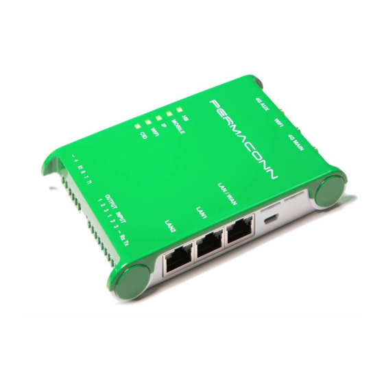
Summary of Contents for Permaconn PM54
- Page 1 PM54 Installation Manual Australia RDCCO Pty Ltd Unit 3/9 – 11 South Street Rydalmere NSW 2116 +61 2 9352 1777 Email: support@permaconn.com Web: www.permaconn.com...
-
Page 2: Table Of Contents
What's in the box………………………………………………………………………………….4 Installation Procedure PM54 ..................5-6 Programming the Alarm Panel / Antenna Installation............6 Device Outputs / Device Inputs..................7 PM54 Alarm Panel Connection / Resetting the PM54 / Activating the PM54.....8 PM54 - LED Status Indicators ....................9 Serial Interface........................10 Upload / Download......................11 IP Setup........................12-17... -
Page 3: Introduction / Features
The Permaconn PM54 is a market leading next-generation connectivity solution for any network- ready device or computer system. The PM54 is a 3 in 1 device that combines an alarm communi- cator with a high-speed 4G router (gateway) and a Wi-Fi hotspot. This allows devices on clients‘... -
Page 4: Atlas Web Platform / Poll Plans / Data Plans
Atlas Web Platform Atlas is a secure web portal that enables users to activate, interrogate and configure Permaconn communicators and routers remotely for diagnostic and control purposes. This portal can be accessed via the web using any Smartphone, Tablet or PC. -
Page 5: Installation Procedure Pm54
If you are using the on-site internet, connect a CAT5/6 cable between the PM54 WAN port and the local router or network point. The PM54 will automatically obtain an IP address if it is set to DHCP (Reset). ... -
Page 6: Programming The Alarm Panel / Antenna Installation
Installation Procedure cont.. The PM54 obtains the Panel Account number directly from the Alarm Panel after the first valid contact ID event is sent. If a fixed Panel Account number is required - inform the Monitoring Centre before activation. -
Page 7: Device Outputs / Device Inputs
Outputs are ‗Open Collector‘ @50mA switching 12vDC negative—for heavier loads a re- lay must be used. Ensure there is a common negative between the PM54 and the device being switched. The outputs can be opened, closed or pulsed using the Atlas web portal ... -
Page 8: Pm54 Alarm Panel Connection / Resetting The Pm54 / Activating The Pm54
When resetting the PM54 Do not power cycle device Caution: Depressing the reset button then applying power may damage the device Activating the PM54 The PM54 communicator MUST be activated before it is powered up. Procedure to activate the PM54 Login to Atlas ... -
Page 9: Pm54 - Led Status Indicators
PM54 - LED Status Indicators PM54 - LED Status Indicators Activity Indication Green Flashing Signal strength OK / Processor OK Signal strength low or trying to Red Flashing reconnect Data traffic on 3G/4G Flash Red Only 1 sim working Mobile... -
Page 10: Serial Interface
NB: This is set during activation process PM54 Tecom MCM Icon Siemens Cardax . (IFM-CDX required) Alarm Panel PM54 Concept 2000 / 3000 / 4000 10K resistor must be fitted between +12v and Alarm Panel PM54 Installation Manual v1 RDCCO_2195_E_IN... -
Page 11: Upload / Download
4G or Ethernet connec- PM54 tion. If using Serial Data as a monitoring path: Connect the panel’s dialler to the PM54 to allow for upload / download (PCS) capability, an example of this is the Tecom & Concept panels Up/Dn Monitoring Note: Disable fax machine defeat and call back. -
Page 12: Ip Setup
Connect the PM54 to the on-site internet gateway with a standard CAT5/6 patch lead. The PM54 must be online (via IP or 4G) and accessible in Atlas to make changes. To utilize an on-site internet connection: Navigate to the IP then WAN tab ... - Page 13 WAN disabled (Reset) Utilising the customers‘ internet: 1: Connect a Cat5 / 6 cable between the WAN port on the PM54 to the customers‘ internet router 2: Tick the Enable WAN connection press save. This will cause the PM54 to reset.
- Page 14 Security Mode options Choosing other than none, will prompt for the network key/password WPA-PSK WPA2-PSK WPA-PSK + WPA2-PSK DHCP: Allows the PM54 to automatically obtain an IP address Static: Allows a fixed IP address in the PM54 PM54 Installation Manual v1 RDCCO_2195_E_IN...
- Page 15 Lease Time is how long the IP address is reserved for Configure a Wi-Fi Hotspot to connect wireless clients and sensors Disabled (Reset) Tick box to enable Wi-Fi Enabled Network name as seen by Wi-Fi client devices security setting: WPA-PSK WPA2-PSK WPA-PSK + WPA2-PSK PM54 Installation Manual v1 RDCCO_2195_E_IN...
- Page 16 IP Setup cont..Allow inbound connections to devices that are connected to the PM54 LAN port from the internet Using the standard Data Plan the IP Address Enabled field is hidden. To use the Port forward option, please call Permaconn to obtain a Data Plan containing a Public IP address, there are a limited number available.
- Page 17 IP Setup cont..Port Forwarding example: Using the PM54 as an Internet Router E.g IP 111.111.111.111 Port 8080 E.g IP 192.168.0.222 Port 80 DVR or NVR 8080 192.168.0.222 PM54 Installation Manual v1 RDCCO_2195_E_IN...
-
Page 18: Device Use Cases
This configuration will deliver alarm events to the control room, allow remote UDL of the alarm panel, allow remote management of the Input / Output via Pocket Secure and provide an internet connection to both wireless and Wi-Fi devices connected to the PM54 device. PM54 Installation Manual v1... - Page 19 Input / Output via Pocket Secure and provide an internet connection to devices connected to the PM54 device; (if the internet connection provided by the on -site Wi-Fi router fails). This configuration provides a redundant internet connection. The PM54 can connect to the Wi-Fi router via a cable if convenient otherwise it may connect as a Wi-Fi client to avoid cabling effort.
-
Page 20: Transmission Delay Times
Auxiliary 2 — Auxiliary input alarm on communicator. Auxiliary 3 — Auxiliary input alarm on communicator. Panel ID Clash— When two (2) Permaconn devices are reporting to the same Control Room on the same line number using the same account number. -
Page 21: Permaconn Contact Id Event Template
Permaconn Contact ID Event Template cont…. Special Events generated by the new Permaconn 54 Communicator Event ID Partition Zone Description Data Usage has reached 80% of allowance Data Usage has reached 95% of allowance Data Usage has reached 100% of allowance... -
Page 22: Pm54 Specifications
3 x Open Collector outputs @ 50mA (max). Function control using Atlas web portal and/or Pocket Secure app. Dimensions 110mm (h) x 25mm (d) x 80mm (w) Weight 180g Power 10 to 15V DC Consumption Idle 0.12A @13.8V DC Transmitting: 0.35A @ 13.8V DC PM54 Installation Manual v1 RDCCO_2195_E_IN... -
Page 23: Warning / Liability
The socket-outlet must be installed near the equipment and easily accessible. The unit must only be operated with the supplied antennas. Install the PM54 in a location where no person is closer than 200 mm to the antennas at all times.
Need help?
Do you have a question about the PM54 and is the answer not in the manual?
Questions and answers