Biostar G31-M7 Setup Manual
Hide thumbs
Also See for G31-M7:
- Bios manual (39 pages) ,
- Setup manual (47 pages) ,
- Setup manual (43 pages)
Table of Contents
Advertisement
Available languages
Available languages
Quick Links
All manuals and user guides at all-guides.com
G31-M7 Setup Manual
FCC Information and Copyright
This equipment has been tes ted and found to comply with the limits of a Class
B digital devic e, purs uant to Part 15 of the FCC Rules . T hese limits are designed
to provide reasonable protec tion against harmful interference in a residential
installation. T his equipment generates , uses , and c an radiate radio frequency
energy and, if not ins talled and used in accordance with the instructions , may
cause harmful interference to radio communications . There is no guarantee
that interference will not occur in a particular ins tallation.
The vendor makes no representations or warranties with respec t to the
contents here and s pecially disclaims any implied warranties of merchantability
or fitness for any purpose. Further the vendor reserves the right to revise this
publication and to make c hanges to the c ontents here without obligation to
notify any party beforehand.
D uplication of this publication, in part or in whole, is not allowed without first
obtaining the vendor's approval in writing.
The content of this user's manual is subject to be c hanged without notice and
we will not be res ponsible for any mis takes found in this user's manual. All the
brand and produc t names are trademarks of their respec tive companies .
Advertisement
Table of Contents

Related Manuals for Biostar G31-M7


Summary of Contents for Biostar G31-M7
- Page 1 All manuals and user guides at all-guides.com G31-M7 Setup Manual FCC Information and Copyright This equipment has been tes ted and found to comply with the limits of a Class B digital devic e, purs uant to Part 15 of the FCC Rules . T hese limits are designed to provide reasonable protec tion against harmful interference in a residential installation.
-
Page 2: Table Of Contents
All manuals and user guides at all-guides.com Table of Contents Chapter 1: Introduction.............1 Before You Start..............1 Package Checklist..............1 Motherboard Features............2 Rear Panel Connectors............3 Motherboard Layout ............4 Chapter 2: Hardware Installation........5 Installing Central Processing Unit (CPU)........ 5 FAN Headers................ -
Page 3: Chapter 1: Introduction
All manuals and user guides at all-guides.com G31-M7 CHAPTER 1: INTRODUCTION EFORE T ART Thank you for choosing our product. Before you start installing the motherboard, please make sure you follow the instructions below: Prepare a dry and stable work ing environment with sufficient lighting. -
Page 4: Motherboard Features
All manuals and user guides at all-guides.com Motherboard Manual OT HERBOARD EAT URES SPEC LGA 775 Supports Hyper-Threading / Execute Disable Bit / Intel Core2Duo / Core2Quad / Celeron 4xx Enhanced Intel SpeedStep® / Intel Architecture-64 / / Pentium D / Pentium 4 / Celeron D Extended Memory 64 Technology / Virtualization processor Technology... -
Page 5: Rear Panel Connectors
Audio Jack Provide Audio-In/Out and microphone connection Board Size 195 (W) x 244 (L) mm Biostar Reserves the right to add or remove support for OS Support Windows 2000 / XP / VISTA any OS with or without notice ANEL... -
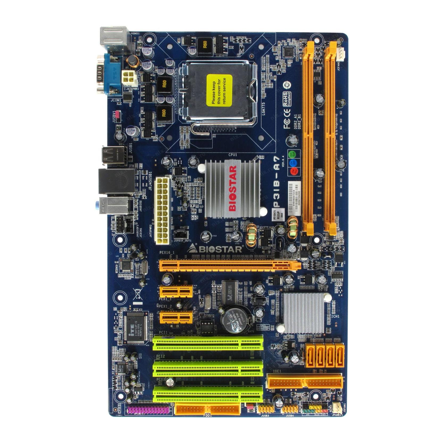
Page 6: Motherboard Layout
All manuals and user guides at all-guides.com Motherboard Manual OT HERBOARD AYOUT JKBMS1 JCFAN1 LGA775 CPU1 JATXPWR1 JATXPWR2 JUSB2 JUS BV1 Intel JRJ45USB1 J AUDIO1 BIOS BAT1 JCDIN1 PEX1_1 JSFAN1 PEX16_1 JCM OS1 S uper I/ O Intel PCI1 ICH7 SATA4 JSPDIF_OU T1 SATA3... -
Page 7: Chapter 2: Hardware Installation
All manuals and user guides at all-guides.com G31-M7 CHAPTER 2: HARDWARE INSTALLATION (CPU) NST ALLING ENT RAL ROCESSING Special Notice: Remove Pin Cap before installation, and make good preservation for future use. When the CPU is removed, cover the Pin Cap on the empty socket to ensure pin legs won’t be damaged. - Page 8 All manuals and user guides at all-guides.com Motherboard Manual Step 2: Look for the triangular cut edge on socket, and the golden dot on CPU should point forwards this triangular cut edge. The CPU will fit only in the correct orientation. Step 2-1: Step 2-2: Step 3: Hold the CPU down firmly, and then lower the lever to locked...
-
Page 9: Fan Headers
All manuals and user guides at all-guides.com G31-M7 FAN H EADERS These fan headers support cooling-fans built in the computer. The fan cable and connector may be different according to the fan manufacturer. Connect the fan cable to the connector while matching the black wire to pin#1. -
Page 10: Installing System Memory
All manuals and user guides at all-guides.com Motherboard Manual NST ALLING YST EM EMORY A. DDR2 module Unlock a DIMM slot by pressing the retaining clips outward. Align a DIMM on the slot such that the notch on the DIMM matches the break on the Slot. - Page 11 All manuals and user guides at all-guides.com G31-M7 B. Memory Capacity DIMM Socket Total Memory DDR2 Module Location Size DDR2_A1 256MB/512MB/1GB/2GB Max is 4B. DDR2_B1 256MB/512MB/1GB/2GB C. Dual Channel Memory Installation To trigger the Dual Channel function of the motherboard, the memory...
-
Page 12: Connectors And Slots
All manuals and user guides at all-guides.com Motherboard Manual 2.4 C ONNECT ORS AND LOT S FDD1: Floppy Disk Connector The motherboard prov ides a standard floppy disk connector that supports 360K, 720K, 1.2M, 1.44M and 2.88M floppy disk ty pes. This connector supports the prov ided f loppy drive ribbon cables. - Page 13 All manuals and user guides at all-guides.com G31-M7 PEX16_1: PCI-Express x16 Slot PCI-Express 1.0a compliant. Maximum theoretical realized bandwidth of 4GB/s simultaneously per direction, f or an aggregate of 8GB/s totally. PEX1_1: PCI-Express x1 Slot PCI-Express 1.0a compliant. Data transf er bandwidth up to 250MB/s per direction; 500MB/s in total.
-
Page 14: Chapter 3: Headers & Jumpers Setup
All manuals and user guides at all-guides.com Motherboard Manual CHAPTER 3: HEADERS & JUMPERS SETUP OW T O ET UP UMPERS The illustration shows how to set up jumpers. When the jumper cap is placed on pins, the jumper is “close”, if not, that means the jumper is “open”. - Page 15 All manuals and user guides at all-guides.com G31-M7 JATXPWR1: ATX Power Source Connector This connector allows user to connect 24-pin power connector on the ATX power supply. Assignment Assignment +3.3V +3.3V -12V +3.3V Ground Ground PS_ON Ground Ground Ground Ground...
- Page 16 All manuals and user guides at all-guides.com Motherboard Manual JUSB3/JUSB4: Headers for USB 2.0 Ports at Front Panel This motherboard prov ides 2 USB 2.0 headers, which allows user to connect additional USB cable on the PC front panel, and also can be connected with internal USB dev ices, like USB card reader.
- Page 17 All manuals and user guides at all-guides.com G31-M7 JCMO S1: Clear CMOS Header By placing the jumper on pin2-3, it allows user to restore the BIOS saf e setting and the CMOS data, please carefully f ollow the procedures to avoid damaging the motherboard.
- Page 18 All manuals and user guides at all-guides.com Motherboard Manual JSPDIF_O UT1: Digital Audio out Connector This connector allows user to connect the PCI bracket SPDIF output header. Assignment SPDIF_OUT Ground JUSBV1/JUSBV2: Power Source Headers for USB Ports Pin 1-2 Close: JUSBV1: +5V for USB ports at JUSB2/JRJ45USB1.
- Page 19 All manuals and user guides at all-guides.com G31-M7 JPRNT1: Printer Port Connector This header allows you to connector printer on the PC. Assignment Assignment -Strobe Ground -ALF Data 6 Data 0 Ground -Error Data 7 Data 1 Ground -Init -ACK...
-
Page 20: Chapter 4: Useful Help
All manuals and user guides at all-guides.com Motherboard Manual CHAPTER 4: USEFUL HELP RIVER NST ALLAT ION OT E After you installed your operating system, please insert the Fully Setup Driver CD into your optical drive and install the driver for better system performance. -
Page 21: Ami Bios Beep Code
All manuals and user guides at all-guides.com G31-M7 4.2 AMI BIO S B Boot Block Beep Codes Number of Beeps Description No media present. (Insert diskette in f loppy drive A:) “AMIBOOT.ROM” f ile not f ound in root directory of diskette in... -
Page 22: Extra Information
All manuals and user guides at all-guides.com Motherboard Manual 4.3 E XT RA NFORMAT ION CPU Overheated If the system shutdown automatically after power on system for seconds, that means the CPU protection function has been activated. When the CPU is over heated, the motherboard will shutdown automatically to avoid a damage of the CPU, and the system may not power on again. - Page 23 All manuals and user guides at all-guides.com G31-M7 BIO-Flasher BIO-Flasher is a BIOS flashing utility prov iding y ou an easy and simple way to update y our BIOS v ia USB pen drive or f loppy disk. The BIO-Flasher is built in the BIOS chip. To enter the utility, press <F12>...
-
Page 24: Troubleshooting
All manuals and user guides at all-guides.com Motherboard Manual 4.4 T ROUBLESHOOT ING Probable Solution No power to the system at all Make sure power cable is Power light don’t illuminate, f an securely plugged in. inside power supply does not turn Replace cable. - Page 25 All manuals and user guides at all-guides.com G31-M7 This page is intentionally left blank.
-
Page 26: Appendencies: Spec In Other Language
All manuals and user guides at all-guides.com Motherboard Manual APPENDENCIES: SPEC IN OTHER LANGUAGE ERMAN Spezifikationen LGA 775 Unterstützt Hyper-Threading / Execute Disable Bit / Intel Core2Duo / Core2Quad / Celeron 4xx Enhanced Intel SpeedStep® / Intel Architecture-64 / / Pentium 4 / Pentium D / Celeron D Extended Memory 64 Technology / Virtualization Prozessoren Technology... - Page 27 Serieller Anschluss Rückseiten-E VGA-Anschluss LAN-Anschluss USB-Anschluss Audioanschluss Platinengröße 195 mm (B) X 244 mm (L) Biostar behält sich das Recht vor , ohne Ankündigung OS-Unterstüt Windows 2000 / XP / VISTA die Unterstützung für ein Betriebssystem zung hinzuzufügen oder zu entfernen.
-
Page 28: France
All manuals and user guides at all-guides.com Motherboard Manual RANCE SPEC LGA 775 Prend en charge les technologies Hyper-Threading / Processeurs Intel Core2Duo / Core2Quad d'exécution de bit de désactivation / Intel SpeedStep® / Celeron 4xx / Pentium 4 / Pentium D / optimisée/ d'architecture Intel 64 / de mémoire Celeron D étendue 64 / de virtualisation... - Page 29 Port USB Fiche audio Dimensions 195 mm (l) X 244 mm (H) de la carte Biostar se réserve le droit d'ajouter ou de supprimer le Support SE Windows 2000 / XP / VISTA support de SE avec ou sans préavis.
-
Page 30: Italian
All manuals and user guides at all-guides.com Motherboard Manual T ALIAN SPECIFICA LGA 775 Supporto di Hyper -Threadi ng / Execute Disable Processore Intel Core 2Duo / Bit / Enhance d I ntel Spee dStep® / Architettura Core2Quad / Celero n 4xx / Penti um 4 Intel 64 / Tecnologia Exte nde d Memory 64 / / Pentium D / Celer on D Tecnolo gia Virtualization... - Page 31 Connettore audio Dimension 195 mm (larghezza) x 244 mm i scheda (altezza) Sistemi Biostar si riserva il diritto di aggiungere o operativi Windows 2000 / XP / VISTA rimuovere il supporto di qualsiasi sistema supportati operativo se nza pre avviso.
-
Page 32: Spanish
All manuals and user guides at all-guides.com Motherboard Manual PANISH Especificación LGA 775 Admite Hyper-Threading / Bit de deshabilitación de Procesador Intel Core2Duo / Core2Quad / ejecución / Intel SpeedStep® Mejorado / Intel Celeron 4xx / Pentium 4 / Pentium D / Architecture-64 / Tecnología Extended Memory 64 / Celeron D Tecnología de virtualización... - Page 33 Tamaño de 195 mm. (A) X 244 Mm. (H) la placa Soporte de Biostar se reserva el derecho de añadir o retirar el Windows 2000 / XP / VISTA sistema soporte de cualquier SO con o sin aviso previo. operativo...
-
Page 34: Portuguese
All manuals and user guides at all-guides.com Motherboard Manual ORT UGUESE ESPECIFICAÇÕES LGA 775 Suporta as tecnologias Hyper-Threading / Execute Processador Intel Core2Duo / Disable Bit / Enhanced Intel SpeedStep® / Intel Core2Quad / Celeron 4xx / Pentium 4 / Arquitecture -64 / Extended Memory 64 / Virtualization Pentium D / Celeron D 533 / 800 / 1066 / 1333 MHz... - Page 35 Tomada de áudio Tamanho 195 mm (L) X 244 mm (A) da placa Sistemas A Biostar reserva-se o direito de adicionar ou remover Windows 2000 / XP / VISTA operativos suporte para qualquer sistema operativo com ou sem suportados aviso prévio.
-
Page 36: Polish
All manuals and user guides at all-guides.com Motherboard Manual OLISH SPEC LGA 775 Obsługa Hyper-Threading / Execute Disable Bit / Procesor Intel Core2Duo / Core2Quad / Enhanced Intel SpeedStep® / Intel Architecture-64 / Procesor Celeron 4xx / Pentium 4 / Pentium D / Extended Memory 64 Technology / Virtualization Celeron D Technology... - Page 37 Back Panel Port VGA Port LAN Port USB Gniazdo audio Wymiary 195 mm (S) X 244 mm (W) płyty Obsluga Biostar zastrzega sobie prawo dodawania lub systemu Windows 2000 / XP / VISTA odwoływania obsługi dowolnego systemu operacyjne operacyjnego bez powiadomienia.
-
Page 38: Russian
All manuals and user guides at all-guides.com Motherboard Manual USSIAN СПЕЦ LGA 775 Поддержка технологий Hyper-Threading / Execute (центральн Процессор Intel Core2Duo / Core2Quad / Disable Bit / Enhanced Intel SpeedStep® / Intel ый Celeron 4xx / Pentium 4 / Pentium D / Architecture-64 / Extended Memory 64 Technology / процессор) Celeron D... - Page 39 ввода-выв USB-порт ода Гнездо для подключения наушников Размер 195 мм (Ш) X 244 мм (В) панели Biostar сохраняет за собой право добавлять или Поддержка Windows 2000 / XP / VISTA удалять средства обеспечения для OS с или без предварительного уведомления.
-
Page 40: Arabic
All manuals and user guides at all-guides.com Motherboard Manual RABIC اﻟﻤﻮاﺻﻔﺎت ﺗﺪﻋﻢ ﺗﻘﻨﻴﺎتHyper-Threading / Execute Disable Bit / LGA 775 Enhanced Intel SpeedStep® / Intel Architecture-64 / ﻣﻌ ﺎ ﻟﺠﺎتIntel Core2Duo / Core2Quad / اﻟﻤﻌ ﺎ ﻟﺠﺔ وﺣﺪة Extended Memory 64 Technology / Virtualization Celeron 4xx / Pentium 4 / Pentium D / اﻟﻤﺮآﺰیﺔ... - Page 41 All manuals and user guides at all-guides.com G31-M7 اﻟﻤﻮاﺻﻔﺎت ﻋﺪد ﻓﺘﺤﺔ ﻋﺪد PCI Express ﻓﺘﺤﺔ اﻟﻔﺘﺤﺎت ﻋﺪد PCI Express x 1 ﻓﺘﺤﺔ ﻋﺪد ﻣﻨﻔﺬ ﻣﺤﺮك أﻗﺮاص ﻣﺮﻥﺔ یﺪﻋﻢ ﻣﺤﺮآﻴﻦ ﻟﻸﻗﺮاص ا ﻟﻤﺮﻥﺔ ﻋﺪد ﻣﻨﻔﺬ ﻃﺎﺑﻌﺔ ﻋﺪد ﻣﻨﻔﺬ یﺪﻋﻢ آﻞ ﻣﻨﻔﺬ اﺙﻨﻴﻦ ﻣﻦ أﺝﻬﺰةIDE ﻋﺪد...
-
Page 42: Japanese
All manuals and user guides at all-guides.com Motherboard Manual APANESE 仕様 LGA 775 Hyper-Threading / Execute Disable Bit / Enhanced Intel Intel Core2Duo / Core2Quad / Celeron 4xx SpeedStep® / Intel Architecture-64 / Extended / Pentium 4 / Pentium D / Celeron D Memory 64 Technology / Virtualization Technologyをサ... - Page 43 All manuals and user guides at all-guides.com G31-M7 仕様 PCIスロット PCI Express x16スロット スロット PCI Express x 1スロット フロッピーコネクタ 各コネクタは2つのフロッピードライブをサポートします プリンタポートコネクタ 各コネクタは1つのプリンタポートをサポートします IDEコネクタ 各コネクタは2つのIDEデバイスをサポートします SATAコネクタ 各コネクタは1つのSATAデバイスをサポートします フロントパネルコネクタ フロントパネル機能をサポートします フロントオーディオコネクタ フロントパネルオーディオ機能をサポートします CDインコネクタ CDオーディオイン機能をサポートします オンボードコ S/PDIFアウトコネクタ デジタルオーディオアウト機能をサポートします ネクタ CPUファンヘッダ CPUファン電源装置(スマートファン機能を搭載) システムファンヘッダ システムファン電源装置...
Need help?
Do you have a question about the G31-M7 and is the answer not in the manual?
Questions and answers