
Related Manuals for ILVE IAG


Summary of Contents for ILVE IAG
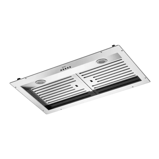
- Page 1 HOODS IAG90 - IAG120 - IAG150 USER – Use and Maintenance INSTALLER - Installation manual cod. EI33960350000EN 12/2021...
- Page 3 INDEX USER (4-13) USEFUL INFORMATION IMPORTANT SAFETY WARNINGS INSTRUCTIONS FOR USE CLEANING AND MAINTENANCE PERIODS OF INACTIVITY ORDINARY MAINTENANCE - replacement of the spotlight INSTALLER (14-31) IMPORTANT SAFETY WARNINGS INSTALLATION IMPORTANT SAFETY WARNINGS INSTALLATION...
-
Page 4: Useful Information
We remain at your full disposal for any further information that you may require, or if you have any problems in understanding any contents of this booklet. ILVE S.p.a. Via Antoniana, 100 35011 Campodarsego (PD) Italy tel. +39 049 9200990 - fax +39 049 9201010 SEND MAIL: mail@ilve.com... - Page 5 USER LEGEND ICON Read this manual carefully before installing or using the equipment. The manual contains some warning or danger symbols: Danger! Situation of immediate danger or dangerous si- tuation that might cause injuries or death. Read the instruction manual Useful advice and information Reference to another chapter ATTENTION:...
-
Page 6: Important Safety Warnings
• ILVE S.p.a. (hereinafter referred to as “the Manufactu- rer”) denies any and all liability due to the failure to comply with the instructions below, including... - Page 7 USER IMPORTANT SAFETY WARNINGS (lights, suction fan) are switched off. • Check fryers during use: overheated oil may catch fire. • Do not ignite open flames or cook flambé foods under the hood. • Never use the hood without the anti-grease filters sup- plied: this could lead to an accumulation of fat and dirt, which could severely harm the operational parts of the product, primarily the blower.
- Page 8 INSTRUCTIONS FOR USE Product’s operation cappa ad external The hood extract fumes and steam generated during evacuazione evacuation cooking from the environment, channelling them through esterna hood metal filters that must be regularly removed and washed. And then, depending on the type of installation, fumes and steam: are driven outside from the building through a drain pipe: this model does not require the use of...
-
Page 9: Timer Function
USER INSTRUCTIONS FOR USE WORKING PANEL LIGHT SWITCH lts function is to switch the light on and off. TIMER BUTTON: (Clock symbol). lts function is to enter the automatic switch off. BUTTON 1: ON/ OFF (turns on and off the engine). lt adjusts the motor to the first speed. RECYCLING AIR 24 HOURS: By pushing button “0/1”... - Page 10 INSTRUCTIONS FOR USE Red LED light TELECOMANDO Blue LED light ON - OFF MOTOR ON - OFF LIGHTING lncrease of motor speed Decrease of motor speed Every signal connected to the motor contlrol enables the BLUE LED lights al the same time for half a second. Every control connected to the light enables the red led light for half a second.
-
Page 11: Cleaning And Maintenance
USER CLEANING AND MAINTENANCE All ordinary maintenance operations must be carried out: • after disconnecting the electric power supply; • always wearing appropriate personal protective equipment (e.g.: gloves, etc...). Failure to follow the instructions, or use of unsuitable products, may pose a risk of fire and/or damage to the equipment or other objects, for which the Manufacturer cannot be held responsible. - Page 12 CLEANING AND MAINTENANCE GREASE METAL FILTERS These filters are usually made in aluminium or stainless steel, and their main purpose is to block the particles of oil and fat suspended in the cooking fumes. An excessive accumulation of grease inside the filters could cause unpleasant smells and decrease the suction power of the hood.
-
Page 13: Periods Of Inactivity
USER PERIODS OF INACTIVITY When not using the equipment for extended periods of times: • disconnect the equipment from the power supply. • if possible, use a soft cloth to apply a thin layer of Vaseline oil to all stainless steel surfaces. - Page 14 IMPORTANT SAFETY WARNINGS WARNING: This appliance must be grounded. In the event of an electrical short circuit, grounding reduces the risk of electric shock by providing an escape wire for the electric current. This appliance is equipped with a cord having a grounding wire with a grounding plug.
- Page 15 INSTALLER IMPORTANT SAFETY WARNINGS If the SUPPLY CORD is damaged, it must be replaced by the manufacturer, its ervice agent or similarly qualified persons in order to avoid a hazard.” Before installing the equipment, carefully read the safety instructions page 6 and the indications provided from page 14.
-
Page 16: Installation
INSTALLATION MOD. Ø EXIT HOLE SUCTION (mm) IAG90 1000 IAG120 1000 IAG150 1000... -
Page 17: Contenuto Imballo
INSTALLER INSTALLATION NECESSARY TOOLS UTENSILI NECESSARI ø8 mm ø 0 5/16” PACKAGE CONTENT CONTENUTO IMBALLO... - Page 18 INSTALLATION Cappa ad evaquazione esterna Hood with external exhaust motor with upper outlet hob motore con foro motor with wall outlet hole d’uscita superiore motore con foro d’uscita a parete cornice porta ltri (metallici) cornice porta ltri (metallici) filter holder frame filter holder frame STEP 1 - STEP 1 -...
- Page 19 INSTALLER INSTALLATION STEP 2 remove the metal filters toglire i ltri metallici STEP 3 (A - B) avvicinare la cornice alla cappa bring the frame closer to the hood...
- Page 20 INSTALLATION STEP 4 fix the frame to the hood with the appropriate screws (not supplied) in the marked holes ssare la cornice alla cappa con le apposite viti (non fornite) nei fori evidenziati STEP 5 replace the metal filters rimettere i ltri metallici...
- Page 21 INSTALLER INSTALLATION Cappa a ricircolo interno Internal recirculation hood motore con ltri Motor with activated carbon ai carboni filters cornici porta ltri (metallici) filter holder frame STEP 1 Fissare il motore con il foro d’uscita verso l’alto face the motor with the outlet hole upwards and secure it (viti non fornite)
- Page 22 INSTALLATION STEP 2 remove the metal filters toglire i ltri metallici STEP 3 (A - B) bring the frame closer to the avvicinare la cornice alla cappa hood...
- Page 23 INSTALLER INSTALLATION STEP 4 fix the frame to the hood with the appropriate screws (not supplied) in the marked holes ssare la cornice alla cappa con le apposite viti (non fornite) nei fori evidenziati STEP 5 replace the metal filters rimettere i ltri metallici...
- Page 24 IMPORTANT SAFETY WARNINGS The installation and extraordinary maintenance operations must be carried out by qualified personnel, authorized by the Manufacturer, having the necessary product knowledge, and in compliance with the regulations in force in the Country of use regarding the types of systems involved and safety in the workplace.
- Page 25 INSTALLER IMPORTANT SAFETY WARNINGS In order to prevent any loss in the product efficiency and safety of use, the hood should be installed indoor only, sheltered from weathering (i.e., rain, wind) and harsh environmental conditions (dried salt, extreme thermal excursion); Do not change the electrical, mechanical and functional structure of the equipment.
-
Page 26: Preliminary Inspection
INSTALLATION PRELIMINARY Fig. 1. INSPECTION After opening the package, please inspect the equipment for any possible damage that could have occurred during transport. If the product is damaged, please take note of the data printed on the product label (Fig. 3.) and promptly notify the data to your Supplier. - Page 27 INSTALLER INSTALLATION HOW TO READ PRODUCT LABEL The product label is located inside the hood, usually attached on its bottom, being visible after the removal of the anti-grease filters. The label shows essential data and information about the product regarding installation, customer service and warranty-related repair, as well as instructions to dete mine the correct spare parts for the specific model.
-
Page 28: Correct Positioning
INSTALLATION CORRECT POSITIONING The hood should be placed at a minimum distance of ELECTRIC CONNECTION 65 cm for the wall-mounted models and 75 cm The electric connection can only be carried for the island/roof models. It could be that Your out by qualified personnel (electrician).The specific hob requires the range hood to be placed at a cable and the internal hood cables must... - Page 29 INSTALLER INSTALLATION FUME EXHAUST CONNECTION cappa ad external evacuazione evacuation esterna hood DUCTING/SUCTION VERSION This type of hood is equipped with a top air outlet for discharge of fumes outside the house, which has to be connected with the inlet of the building chimney, com- monly through a hose.
- Page 30 NOTES...
Need help?
Do you have a question about the IAG and is the answer not in the manual?
Questions and answers