Table of Contents
Advertisement
Quick Links
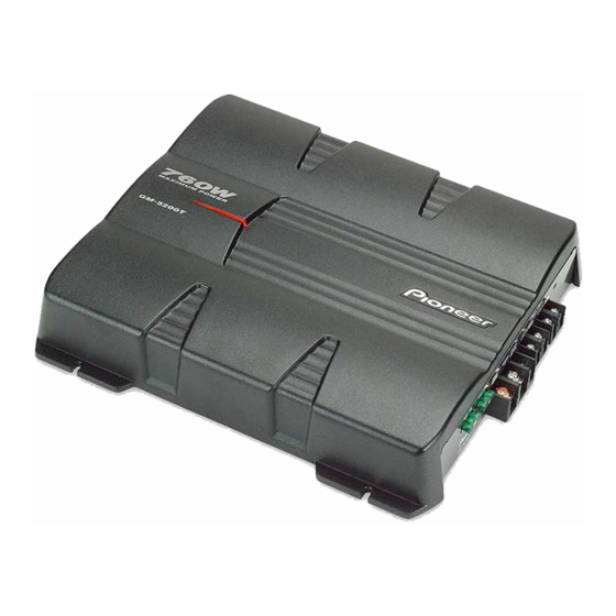
BRIDGEABLE TWO-CHANNEL POWER AMPLIFIER
GM-5200T
GM-5200T
GM-5200T
GM-5200T
This service manual should be used together with the following manual(s) listed below.
For the parts numbers, adjustments, etc. which are not shown in this manual,
refer to the following manual(s).
Model No.
GM-520T/XU/UC
PIONEER CORPORATION
PIONEER ELECTRONICS (USA) INC. P.O. Box 1760, Long Beach, CA 90801-1760, U.S.A.
PIONEER EUROPE NV Haven 1087, Keetberglaan 1, 9120 Melsele, Belgium
PIONEER ELECTRONICS ASIACENTRE PTE. LTD. 253 Alexandra Road, #04-01, Singapore 159936
PIONEER CORPORATION 2005
/XU/EW
/XU/ES
/XU/CN
Order No.
Mech. Module
CRT3519
4-1, Meguro 1-chome, Meguro-ku, Tokyo 153-8654, Japan
ORDER NO.
CRT3560
/XU/UC
Remarks
K-ZZA. OCT. 2005 Printed in Japan
Advertisement
Table of Contents

Related Manuals for Pioneer GM-520T/XU/UC


Summary of Contents for Pioneer GM-520T/XU/UC
- Page 1 PIONEER CORPORATION 4-1, Meguro 1-chome, Meguro-ku, Tokyo 153-8654, Japan PIONEER ELECTRONICS (USA) INC. P.O. Box 1760, Long Beach, CA 90801-1760, U.S.A. PIONEER EUROPE NV Haven 1087, Keetberglaan 1, 9120 Melsele, Belgium PIONEER ELECTRONICS ASIACENTRE PTE. LTD. 253 Alexandra Road, #04-01, Singapore 159936 PIONEER CORPORATION 2005 K-ZZA.
- Page 2 California to cause cancer, birth defects or other reproductive harm. Health & Safety Code Section 25249.6 - Proposition 65 EXPLODED VIEWS AND PARTS LIST PACKING(Page 6) PACKING SECTION PARTS LIST *:Non spare part Mark No. Description GM-520T/XU/UC GM-5200T/XU/UC Carton CHG5587 CHG5586 Contain Box CHL5587 CHL5586...
- Page 3 English, Spanish, German, French, Italian, Dutch, Russian CRD4012 English, Spanish CRD4013 Arabic, Portuguese(B) CRB2106 Traditional Chinese EXTERIOR(Page 8) EXTERIOR SECTION PARTS LIST GM-5200T/XU/UC Mark No. Description GM-520T/XU/UC GM-5200T/XU/ES GM-5200T/XU/CN Panel CNB3202 CNB3312 Heat Sink CNR1828 CNR1829 12 Amp Unit CWH1287 CWH1325...
- Page 4 PIONEER CORPORATION 4-1, Meguro 1-chome, Meguro-ku, Tokyo 153-8654, Japan PIONEER ELECTRONICS (USA) INC. P.O. Box 1760, Long Beach, CA 90801-1760, U.S.A. PIONEER EUROPE NV Haven 1087, Keetberglaan 1, 9120 Melsele, Belgium PIONEER ELECTRONICS ASIACENTRE PTE. LTD. 253 Alexandra Road, #04-01, Singapore 159936 PIONEER CORPORATION 2005 K-ZZA.
-
Page 5: Safety Information
Health & Safety Code Section 25249.6 - Proposition 65 - Service Precaution You should conform to the regulations governing the product (safety, radio and noise, and other regulations), and should keep the safety during servicing by following the safety instructions described in this manual. GM-520T/XU/UC... - Page 6 To protect products from damages or failures during transit, the shipping mode should be set or the shipping screws should be installed before shipment. Please be sure to follow this method especially if it is specified in this manual. GM-520T/XU/UC...
-
Page 7: Table Of Contents
4. PCB CONNECTION DIAGRAM ........................16 4.1 AMP UNIT ..............................16 5. ELECTRICAL PARTS LIST ..........................20 6. ADJUSTMENT ............................... 24 7. GENERAL INFORMATION ..........................25 7.1 DIAGNOSIS ............................. 25 7.1.1 DISASSEMBLY ............................. 25 7.1.2 CONNECTOR FUNCTION DESCRIPTION ..................26 8. OPERATIONS ..............................27 GM-520T/XU/UC... -
Page 8: Specifications
1. SPECIFICATIONS GM-520T/XU/UC... -
Page 9: Exploded Views And Parts List
• Screw adjacent to mark on the product are used for disassembly. • For the applying amount of lubricants or glue, follow the instructions in this manual. (In the case of no amount instructions,apply as you think it appropriate.) 2.1 PACKING GM-520T/XU/UC... - Page 10 Contain Box CHL5587 Screw BYC40P180FTB 9-1 Polyethylene Bag CEG1116 Polyethylene Sheet CNM4338 9-2 Owner's Manual CRD4010 Cord Assy CDE7736 Protector CHP3066 9-3 Card ARY1048 9-4 Caution Card CRP1324 Polyethylene Bag CEG1351 Owner's Manual Part No. Language CRD4010 English, French, Spanish GM-520T/XU/UC...
-
Page 11: Exterior
2.2 EXTERIOR 13 13 GM-520T/XU/UC... - Page 12 CND2470 Buss Bar CND2472 Buss Bar CND2729 Sub Heat Sink CNR1808 Sub Heat Sink CNR1810 Screw PPZ30P100FSN Screw PPZ30P100FTB Terminal (CN850) VNF1084 Screw PPZ30P100FTB > Fuse (FU100, FU101) (30A) CEK1330 Screw BMZ40P200FTB Seal CAN3984 Holder CNV8522 NB40FTB Washer WB40FTB GM-520T/XU/UC...
-
Page 13: Block Diagram And Schematic Diagram
No differentiation is made between chip capacitors and ← 0.022 R022 discrete capacitors. Guide page -1.7dB ~ Detailed page 0dB or +12dB or +6dB -32.1dB -13.8dBs +18.3dBs -1.8d +18.3dBs +18.5dBs (BB ON INPUT MAX) BASS BOOST GAIN BASS BOOST GAIN GM-520T/XU/UC... - Page 14 AMP UNIT 0dB or +12dB or +6dB -1.8dBs -3.1dBs +38.5dBs BASS BOOST DTC643TU DTC643TU BASS BOOST > 8R2K > 8R2K GM-520T/XU/UC...
- Page 15 GM-520T/XU/UC...
- Page 16 GM-520T/XU/UC...
- Page 17 GM-520T/XU/UC...
- Page 18 GM-520T/XU/UC...
-
Page 19: Pcb Connection Diagram
2.Viewpoint of PCB diagrams Capacitor Connector SIDE A SIDE B P.C.Board Chip Part 3 2 1 3 2 1 3 2 1 3 2 1 3 2 1 3 2 1 GM-520T/XU/UC... - Page 20 SIDE A BASS BOOST GAIN LPF/OFF RCA IN SPEAKER LEBEL INPUT 3 2 1 GM-520T/XU/UC...
- Page 21 AMP UNIT GM-520T/XU/UC...
- Page 22 SIDE B GM-520T/XU/UC...
-
Page 23: Electrical Parts List
Q 582 (A,240,163) Transistor 2SC3421 D 556 (B,234,145) Diode MA111 D 557 (B,247,71) Diode MA111 Q 583 (A,276,34) Transistor 2SC4388 D 558 (B,226,121) Diode MA111 Q 584 (A,250,199) Transistor 2SC4388 D 601 (B,247,117) LED FR1112H Q 585 (A,254,34) Transistor 2SC4388 GM-520T/XU/UC... - Page 24 R 176 (B,301,180) RS1/16S221J R 586 (A,245,202) RD1/2PM100J R 177 (B,316,178) RS1/16S121J R 587 (A,258,31) RD1/2PM100J R 178 (B,301,182) RS1/16S132J R 588 (A,224,202) RD1/2PM100J R 179 (B,316,182) RS1/16S122J R 589 (B,238,30) RS1/16S221J R 180 (B,301,183) RS1/16S104J R 590 (B,213,205) RS1/16S221J GM-520T/XU/UC...
- Page 25 C 562 (B,222,127) CCSRCH150J50 R 951 (A,139,197) RD1/4PU103J C 563 (B,228,70) CCSRCH470J50 R 952 (A,112,190) RD1/4PU103J C 564 (B,244,158) CCSRCH470J50 C 565 (A,230,65) CFTNA223J50 R 953 (A,142,198) RD1/2PM470J R 954 (A,118,201) RD1/2PM470J C 566 (A,218,157) CFTNA223J50 R 961 (A,115,109) RD1/2PM220J GM-520T/XU/UC...
- Page 26 C 972 (A,167,64) CEAT101M16 C 973 (A,151,74) CQHA102J2A C 974 (A,144,72) CEAT221M16 C 975 (A,132,74) CEANP470M16 C 980 (A,144,53) CFTNA103J50 C 991 (A,145,179) CEAT471M50(P45) C 992 (A,120,177) CEAT471M50(P45) C 993 (A,135,173) CQHA102J2A C 994 (A,130,173) CQHA102J2A C 999 (B,248,126) CKSRYB224K16 GM-520T/XU/UC...
-
Page 27: Adjustment
6. ADJUSTMENT There is no information to be shown in this chapter. GM-520T/XU/UC... -
Page 28: General Information
7. GENERAL INFORMATION 7.1 DIAGNOSIS 7.1.1 DISASSEMBLY Removing the Case (Fig.1) Remove the six screws and then remove the Case. Case Fig.1 Removing the Amp Unit (Fig.2) Remove the fifteen screws and then remove the Amp Unit. Amp Unit Fig.2 GM-520T/XU/UC... -
Page 29: Connector Function Description
7.1.2 CONNECTOR FUNCTION DESCRIPTION GM-520T/XU/UC... -
Page 30: Operations
8. OPERATIONS GM-520T/XU/UC... - Page 31 GM-520T/XU/UC...
- Page 32 GM-520T/XU/UC...
Need help?
Do you have a question about the GM-520T/XU/UC and is the answer not in the manual?
Questions and answers