Pioneer GM-5400T Service Manual
Bridgeable two-channel power amplifier
Hide thumbs
Also See for GM-5400T:
- Owner's manual (96 pages) ,
- Owner's manual (17 pages) ,
- Owner's manual (41 pages)
Table of Contents
Advertisement
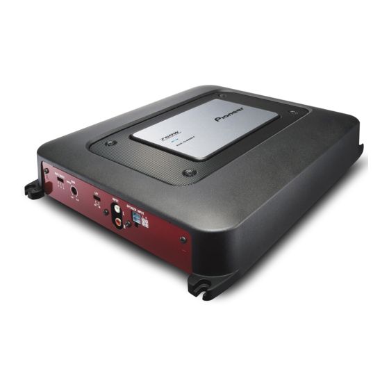
BRIDGEABLE TWO-CHANNEL POWER AMPLIFIER
GM-5400T
GM-5400T
GM-5400T
For details, refer to "Important Check Points for Good Servicing".
PIONEER CORPORATION
PIONEER ELECTRONICS (USA) INC. P.O. Box 1760, Long Beach, CA 90801-1760, U.S.A.
PIONEER EUROPE NV Haven 1087, Keetberglaan 1, 9120 Melsele, Belgium
PIONEER ELECTRONICS ASIACENTRE PTE. LTD. 253 Alexandra Road, #04-01, Singapore 159936
PIONEER CORPORATION 2008
/XJ/EW5
/XJ/ES
4-1, Meguro 1-chome, Meguro-ku, Tokyo 153-8654, Japan
GM-5400T/XJ/UC
ORDER NO.
CRT4251
/XJ/UC
K-ZZZ. NOV. 2008 Printed in Japan
Advertisement
Table of Contents

Related Manuals for Pioneer GM-5400T


Summary of Contents for Pioneer GM-5400T
- Page 1 PIONEER CORPORATION 4-1, Meguro 1-chome, Meguro-ku, Tokyo 153-8654, Japan PIONEER ELECTRONICS (USA) INC. P.O. Box 1760, Long Beach, CA 90801-1760, U.S.A. PIONEER EUROPE NV Haven 1087, Keetberglaan 1, 9120 Melsele, Belgium PIONEER ELECTRONICS ASIACENTRE PTE. LTD. 253 Alexandra Road, #04-01, Singapore 159936 PIONEER CORPORATION 2008 K-ZZZ.
-
Page 2: Safety Information
Where in a manufacturer’s service documentation, for example in circuit diagrams or lists of components, a symbol is used to indicate that a specific component shall be replaced only by the component specified in that documentation for safety reasons, the following symbol shall be used: GM-5400T/XJ/UC... - Page 3 To protect products from damages or failures during transit, the shipping mode should be set or the shipping screws should be installed before shipment. Please be sure to follow this method especially if it is specified in this manual. GM-5400T/XJ/UC...
-
Page 4: Table Of Contents
9. EXPLODED VIEWS AND PARTS LIST......................12 9.1 PACKING ..............................12 9.2 EXTERIOR............................... 14 10. SCHEMATIC DIAGRAM ..........................16 10.1 AMP UNIT(GUIDE PAGE) ........................16 11. PCB CONNECTION DIAGRAM........................22 11.1 AMP UNIT .............................. 22 12. ELECTRICAL PARTS LIST .......................... 26 GM-5400T/XJ/UC... -
Page 5: Service Precautions
Compared with eutectic solders, lead-free solders have higher bond strengths but slower wetting times and higher melting temperatures (hard to melt/easy to harden). The following lead-free solders are available as service parts: Parts numbers of lead-free solder: GYP1006 1.0 in dia. GYP1007 0.6 in dia. GYP1008 0.3 in dia. GM-5400T/XJ/UC... -
Page 6: Specifications
2. SPECIFICATIONS 2.1 SPECIFICATIONS GM-5400T/XJ/UC CEA2006 Specifications Power source......14.4 V DC (10.8 V to 15.1 V allowable) Grounding system....Negative type Current consumption ..30 A (atcontinuous power, 4 ? ) Average current drawn..10 A (4 for two channels) - Page 7 GM-5400T/XJ/EW5, GM-5400T/XJ/ES working out total current drawn by multiple Power source......14.4 V DC (10.8 V to 15.1 V power amplifiers. allowable) Grounding system....Negative type Current consumption ..30 A (atcontinuous power, Average current drawn..10 A (4 for two channels)
-
Page 8: Panel Facilities
2.2 PANEL FACILITIES NORMAL position. For use with an RCA What ’s what equipped Pioneer car stereo, with max. Front side output of 4 V or more, adjust level to match that of the car stereo output. • If you hear too much noise when using the speaker input terminals, turn the gain control to higher level. -
Page 9: Connection Diagram
4 External output If only one input plug is used, do not connect anything to RCA input jack B. (ES) 5 Connecting wire with RCA pin plugs (sold se- parately) 6 Speaker input terminal 7 RCA input jack GM-5400T/XJ/UC... -
Page 10: Basic Items For Service
Volume too high Volume fluctuating Sound interrupted 4. BLOCK DIAGRAM There is not information to be shown in this chapter. 5. DIAGNOSIS 5.1 CONNECTOR FUNCTION DESCRIPTION 6. SERVICE MODE There is not information to be shown in this chapter. GM-5400T/XJ/UC... -
Page 11: Disassembly
Chassis. Fig.1 Removing the Amp Unit (Fig.2) Remove the twenty four screws and then remove the Chassis. Amp Unit Fig.2 Bonding Position GYL1006 8. EACH SETTING AND ADJUSTMENT There is not information to be shown in this chapter. GM-5400T/XJ/UC... -
Page 12: Exploded Views And Parts List
Screw adjacent to mark on the product are used for disassembly. For the applying amount of lubricants or glue, follow the instructions in this manual. (In the case of no amount instructions,apply as you think it appropriate.) 9.1 PACKING GM-5400T/XJ/UC... - Page 13 Polyethylene Bag CZE2962 Screw BYC40P180FTB Polyethylene Sheet CNM4338 Polyethylene Bag See Contrast table (2) (2) CONTRAST TABLE GM-5400T/XJ/UC, GM-5400T/XJ/EW5 and GM-5400T/XJ/ES are constructed the same except for the following: Mark Description GM-5400T/XJ/UC GM-5400T/XJ/EW5 GM-5400T/XJ/ES Caution Card CZR5560 Not used Not used...
-
Page 14: Exterior
9.2 EXTERIOR GM-5400T/XJ/UC... - Page 15 Bas Bar(3) CZN8427 Earth Terminal(KN801) CZK2969 Screw PBZ30P120FTB Holder CZN8430 Heat Sink CZN8432 (2) CONTRAST TABLE GM-5400T/XJ/UC, GM-5400T/XJ/EW5 and GM-5400T/XJ/ES are constructed the same except for the following: Mark Description GM-5400T/XJ/UC GM-5400T/XJ/EW5 GM-5400T/XJ/ES Screw BMZ40P250FTB Not used Not used Holder...
-
Page 16: Schematic Diagram
- 44.5 + 3 V D-D converter output voltage (VH)-2 + 36.5 + 5 V Rg=1 kohm Referred value - 39.5 + 5 V D-D converter output voltage (VD)-2 + 34.5 + 5 V Rg=1 kohm Referred value - 36.5 + 5 V GM-5400T/XJ/UC... - Page 17 NM : No Mount The > mark found on some component parts indicates the importance of the safety factor of the part. Therefore, when replacing, be sure to use parts of identical designation. AMP UNIT > > GM-5400T/XJ/UC...
- Page 18 GM-5400T/XJ/UC...
- Page 19 EW5,ES GM-5400T/XJ/UC...
- Page 20 GM-5400T/XJ/UC...
- Page 21 GM-5400T/XJ/UC...
-
Page 22: Pcb Connection Diagram
1.The parts mounted on this PCB include all necessary parts for several destination. For further information for respective destinations, be sure to check with the schematic dia- gram. 2.Viewpoint of PCB diagrams Capacitor Connector SIDE A SIDE B Chip Part P.C.Board GM-5400T/XJ/UC... - Page 23 SIDE A GM-5400T/XJ/UC...
- Page 24 AMP UNIT GM-5400T/XJ/UC...
- Page 25 SIDE B GM-5400T/XJ/UC...
-
Page 26: Electrical Parts List
Q 518 Transistor KTD600K D 103 Diode 1SS355 Q 519 Transistor KTB631K D 104 Diode 1SS355 Q 520 Transistor KTB631K D 105 Diode 1SS355 Q 521 Transistor KTC3911S D 106 Diode 1SS355 Q 522 Transistor KTC3911S D 107 Diode 1SS355 GM-5400T/XJ/UC... - Page 27 R 537 RS1/16S473J R 114 RS1/16S0R0J R 538 RS1/16S473J R 115 RS1/16S0R0J R 539 RD1/2PM100J R 116 RS1/16S0R0J R 540 RD1/2PM100J R 117 RS1/16S103J R 541 RS1/16S473J R 118 RS1/16S103J R 542 RS1/16S473J R 121 RS1/8S683J R 543 RS1/16S564J GM-5400T/XJ/UC...
- Page 28 R 737 RS1/16S331J C 108 CCSRCH470J50 R 738 RS1/16S473J C 109 CFTLA223J50 R 742 RS1/16S334J C 110 CFTLA223J50 C 111 CEAT330M16 R 743 RS1/16S472J C 112 CEAT330M16 R 750 RS1/16S513J R 751 RS1/16S473J C 113 CCSRCH221J50 R 752 RS1/16S332J GM-5400T/XJ/UC...
- Page 29 C 807 CKSRYB224K16 C 808 CKSRYB472K50 C 809 CKSRYB472K50 C 810 3 300 uF/16 V CZC2977 C 811 3 300 uF/16 V CZC2977 C 812 CCSRCH222J50 C 815 CEAT221M50 C 816 CEAT221M50 C 819 2 200 uF/50 V CZC2976 GM-5400T/XJ/UC...
Need help?
Do you have a question about the GM-5400T and is the answer not in the manual?
Questions and answers