Table of Contents
Advertisement
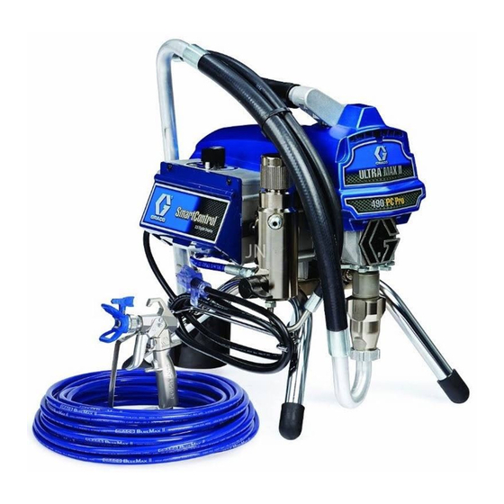
Operation, Parts
Electric Airless
Sprayers
For professional use only.
Not approved for use in explosive atmospheres or hazardous locations.
For portable airless spraying of architectural paints and coatings.
490/495/595/395EU Models:
3300 psi (228 bar, 22.8 MPa) Maximum Working Pressure
See page 3 for additional model information.
Important Safety Instructions
Read all warnings and instructions in this manual and related manuals.
Be familiar with the controls and the proper usage of the equipment.
Save these instructions.
Gun – 311861 (Contractor/FTx) 312830 (SG3)
Use only genuine Graco replacement parts.
The use of non-Graco replacement parts may void warranty.
Related Manuals
Pump – 334599
334530E
EN
ti24941a
Advertisement
Table of Contents


Need help?
Do you have a question about the 17С327 and is the answer not in the manual?
Questions and answers