Table of Contents
Advertisement
https://appliancetechmanuals.com
This service manual is intended for use by persons having electrical and mechanical training
and a level of knowledge of these subjects generally considered acceptable in the appliance
repair trade. Electrolux Home Products cannot be responsible, nor assume any liability, for
injury or damage of any kind arising from the use of this manual.
Publication # 5995528261
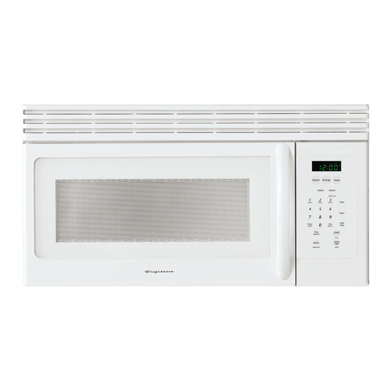
OVER THE RANGE MICROWAVE OVEN
SERVICE MANUAL
Models
FMV157GS
FMV157GB
FMV157GM
FMV157GQ
FMV157GC
! ATTENTION !
November 2008
CFMV157GS
CFMV157GB
CFMV157GM
CFMV157GQ
CFMV157GC
Part # 316439269
Advertisement
Table of Contents


Need help?
Do you have a question about the FMV157GS and is the answer not in the manual?
Questions and answers