Table of Contents
Advertisement
Quick Links
Preface
Thanks for your favor in our product. This manual is helpful for you to quickly know how to use the
product. For detailed features and operations, please refer to the Feature Description and Operation
Manual along with the product.
To avoid body injury or property loss caused by misoperation, please read the Safety Information
Booklet carefully before use.
This manual is applicable to the following product:
MD62X Digital Mobile Radio (X may represent 2, 5, 6 or 8)
Advertisement
Table of Contents

Related Manuals for Hytera MD62X


Summary of Contents for Hytera MD62X
- Page 1 Manual along with the product. To avoid body injury or property loss caused by misoperation, please read the Safety Information Booklet carefully before use. This manual is applicable to the following product: MD62X Digital Mobile Radio (X may represent 2, 5, 6 or 8)
- Page 2 Functions marked with no icon are available on both analog and digital channels. Disclaimer Hytera Communications Corporation Limited (the Company) endeavors to achieve the accuracy and completeness of this manual, but no warranty of accuracy or reliability is given. All the specifications and designs are subject to change without notice due to continuous technology development.
- Page 3 RF Radiation Information This product must be restricted to operations in an occupational/controlled RF exposure environment. Users must be fully aware of the hazards of the exposure and able to exercise control over their RF exposure to qualify for the higher exposure limits. RF Radiation Profile Radio Frequency (RF) is a frequency of electromagnetic radiation in the range at which radio signals are transmitted.
- Page 4 EU Regulatory Conformance As certified by the qualified laboratory, the product is in compliance with the essential requirements and other relevant provisions of the Directive 1999/5/EC. Please note that the above information is applicable to EU countries only.
-
Page 5: Table Of Contents
Contents 1. Items in the Package .......................... 1 2. Product Overview ..........................1 2.1 Front Panel ............................. 2 2.2 Rear Panel ............................3 2.3 Programmable Keys ........................3 2.4 LCD Icon ............................3 2.5 LED Indicator ..........................4 3. Installation ............................5 3.1 Instructions ............................. -
Page 6: Items In The Package
1. Items in the Package Please unpack carefully and check if all items listed below are received. If any item is missing or damaged, please contact your dealer. Radio Palm Microphone Microphone Hanger and Screws Mounting Bracket Kit Fuse Documentation Kit Power Cord Note The frequency band is marked on the label of antenna;... -
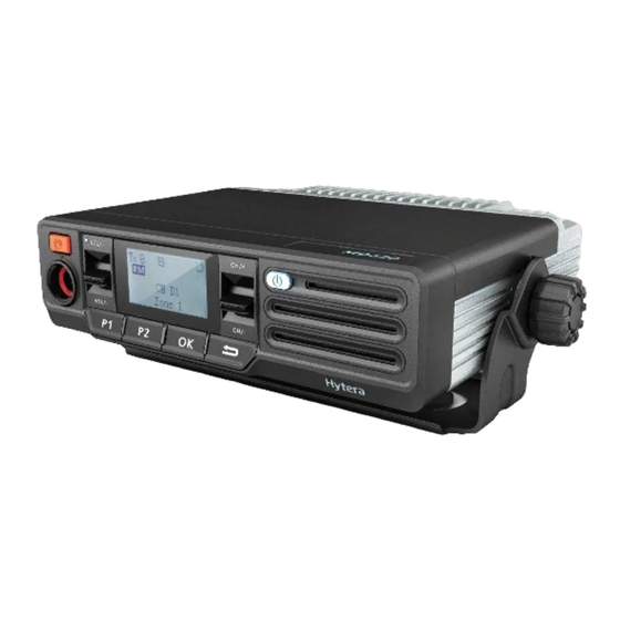
Page 7: Product Overview
2. Product Overview Front Panel Part Name Part Name Volume Control Speaker LED Indicator Programmable Keys LCD Display Microphone Connector Programmable Keys Microphone Installation Index Channe selector Power On/Off Key... -
Page 8: Rear Panel
GPS Antenna Connector (SMA Power Inlet female) Note: The GPS antenna connector is available for MD62X mobile radios only. Programmable Keys For enhanced convenience, you may request your dealer to program the SK1, SK2, P1, P2 and P3 keys as shortcuts to certain feature. -
Page 9: Led Indicator
Icon Radio Status The radio is roaming. The radio is scanning. More bars indicate stronger signal strength. LED Indicator LED Indication Radio Status The LED indicator flashes Powering on green. The LED indicator glows Transmitting red. The LED indicator glows Receiving green. -
Page 10: Installation
3. Installation Instructions Before you install the radio in a vehicle, be sure to read the following instructions carefully: The radio must work with a13.6V ± 15% negative ground electrical system only. Ensure to check the ground polarity and voltage of the vehicle power supply prior to installation. ... -
Page 11: Installation Parts
Installation Parts Part Name Part Name Radio Power Inlet Locking Knobs Power Cord (black) Mounting Bracket Power Cord (red) 4.8 * 20mm Self-tapping Screws Fuse Palm Microphone RF Antenna Connector... -
Page 12: Installation Procedure
Part Name Part Name 4 * 16mm Self-tapping Screws GPS Antenna Connector Microphone Hanger Installation Procedure 1. Install the bracket in a location where you can operate the radio conveniently. 2. Connect accessories such as the antenna and power cord to the radio. 3. -
Page 13: Basic Operations
4. Basic Operations Turning the Radio On/Off Long press Power On/Off key to turn the radio on and off. Adjusting the Volume After the radio is powered on,turn the volume menu up increase the voice volume, turn the volume menu down is to decease it. -
Page 14: Call Services
5. Call Services After the radio is powered on, you can make and receive calls. To ensure optimal volume of the receiving radio, keep the microphone about 2.5 to 5 centimeters away from your mouth when the radio is transmitting. Private Call 5.1.1 Initiating a Private Call... -
Page 15: Group Call
Manual Dial Step 1 Go to “Menu -> Contact -> Manual Dial”. Step 2 Input the private call number using the numeric keypad. Step 3 Hold down the PTT key to initiate a private call. Note If both the Private Call Manual Dial and Group Call Manual Dial are available, you can press ... -
Page 16: Call On Analog Channel (Without Signaling)
5.2.2 Receiving and Responding to a Group Call When you receive a group call, the radio will display the icon on the LCD. You can hold down the PTT key to call back within the preset time. Call on Analog Channel (Without Signaling) To transmit on an analog channel, hold down the PTT and speak into the microphone. -
Page 17: Troubleshooting
6. Troubleshooting Phenomena Analysis Solution The radio cannot power cord Connect the power cord properly. be powered on. disconnected. Increase the volume by rotating the Volume The volume level may be low. Control knob . During receiving, the voice is weak, The antenna may get loose or Turn off the radio and reattach the antenna. - Page 18 Phenomena Analysis Solution locate unfavorable position. example, your communication Move to an open and flat area, and restart the blocked high radio to try again. buildings or frustrated in the underground areas. You may suffer from external Stay away from equipment that may cause disturbance (such interference.
-
Page 19: Care And Cleaning
7. Care and Cleaning To guarantee optimal performance as well as a long service life of the product, please follow the tips below. Product Care Do not pierce or scrape the product. Keep the product far away from substances that can corrode the circuit. ... -
Page 20: Optional Accessories
8. Optional Accessories The following items are the main optional accessories for the product, and please consult your local dealer for more other accessories. Caution: Use the accessories specified by the Company only. If not, the Company shall not be liable for any loss or damage arising out of use of unauthorized accessories. - Page 21 Type Model Name RCC05 Mobile Radio Remote Mount Kit (6 meters)(IP67) RCC06 Mobile Radio Remote Mount Kit (3 meters)(IP54) RCC07 Mobile Radio Remote Mount Kit (6 meters)(IP54) Omni-directional Antenna...
- Page 22 9. Technical parameters Operation From 400MHz to 470MHz Frequency Range: Rated Output Power: High Power: 45W (46.53dBm)/Low Power: 5W (36.99dBm) Modulation Type: Analog Voice: Digital Voice/Digital Data: 4FSK Digital Type: Channel Separation: Analog Voice: 12.5kHz 25kHz Digital Voice/Digital Data: 12.5kHz Emission Designator: Analog Voice: 12.5kHz Channel Separation: 9K89F3E...
- Page 23 10. FCC STATEMENT This device complies with Part 15 of the FCC Rules. Operation is subject to the following two conditions: (1) This device may not cause harmful interference, and (2) this device must accept any interference received, including interference that may cause undesired operation. NOTE 1: This equipment has been tested and found to comply with the limits for a Class B digital device, pursuant to part 15 of the FCC Rules. These limits are designed to provide reasonable protection against harmful interference in a residential installation. This equipment generates, uses and can radiate radio frequency energy and, if not installed and used in accordance with the instructions, may cause harmful interference to radio communications. However, there is no guarantee that interference will not occur in a particular installation. If this equipment does cause harmful interference to radio or television reception, which can be determined by turning the equipment off and on, the user is encouraged to try to correct the interference by one or more of the following measures: ‐ Reorient or relocate the receiving antenna. ‐ Increase the separation between the equipment and receiver. ‐Connect the equipment into an outlet on a circuit different from that to which the receiver is connected. ‐Consult the dealer or an experienced radio/TV technician for help. NOTE 2: Any changes or modifications to this unit not expressly approved by the party responsible for compliance could void the user's authority to operate the equipment. RF radiation safety warnings and the following: Safe Distance, R , (cm) safe Antenna FCC Part 2.1091 Controlled RF Exposure TQC-150CII (5.5dBi) The antenna only can be installed on the roof of the vehicle. ...
- Page 24 11. IC STATEMENT This device complies with Industry Canada licence‐exempt RSS standard(s): Operation is subject to the following two conditions: (1) This device may not cause interference, and (2) This device must accept any interference, including interference that may cause undesired operation of the device. Le présent appareil est conforme aux CNR d'Industrie Canada applicables aux appareils radio exempts de licence. L'exploitation est autorisée aux deux conditions suivantes : (1) l'appareil ne doit pas produire de brouillage, et (2) (2) l'utilisateur de l'appareil doit accepter tout brouillage radioélectrique subi, même si le brouillage est susceptible d'en compromettre le fonctionnement. RF radiation safety warnings and the following: Safe Distance, Rsafe, (cm) Antenna RSS‐102 Controlled Use Devices (Controlled Environment) TQC‐150CII (5.5dBi) 76 Avertissements de sécurité radiologique RF et les éléments suivants: Distance de sécurité, Rsûr, (cm) Antenne RSS‐102 Dispositifs d'utilisation contrôlée (environnement contrôlé) TQC-150CII (5.5dBi) 76 ...
Need help?
Do you have a question about the MD62X and is the answer not in the manual?
Questions and answers