Table of Contents
Advertisement
Quick Links
INSTALLATION &
OPERATION MANUAL
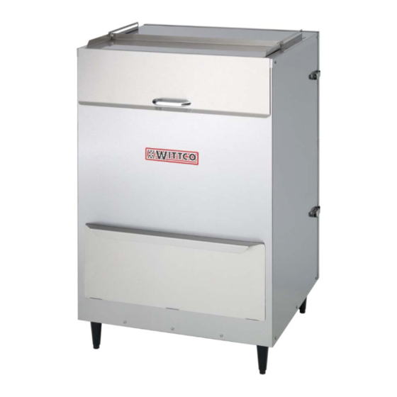
CHIP WARMERS
MODELS:
500-CW
700-CW
For additional information on WITTCO or to locate an authorized parts
and service provider in your area, visit our website at
www.wittco.com
WITTCO FOOD SERVICE EQUIPMENT
7737 NORTH 81 STREET
DIVISION OF ITW FOOD EQUIPMENT GROUP, LLC
MILWAUKEE, WI 53223
www.wittco.com
©
F-41160 (09-12)
2012 Wittco Foodservice Equipment
Advertisement
Table of Contents

Related Manuals for Wittco 500-CW


Summary of Contents for Wittco 500-CW
- Page 1 OPERATION MANUAL CHIP WARMERS MODELS: 500-CW 700-CW For additional information on WITTCO or to locate an authorized parts and service provider in your area, visit our website at www.wittco.com WITTCO FOOD SERVICE EQUIPMENT 7737 NORTH 81 STREET DIVISION OF ITW FOOD EQUIPMENT GROUP, LLC MILWAUKEE, WI 53223 www.wittco.com...
-
Page 2: Important For Your Safety
500 & 700 CHIP WARMER F-41160 (09-12) IMPORTANT FOR YOUR SAFETY THIS MANUAL HAS BEEN PREPARED FOR PERSONNEL QUALIFIED TO INSTALL ELECTRICAL EQUIPMENT, WHO SHOULD PERFORM THE INITIAL FIELD START- UP AND ADJUSTMENTS OF THE EQUIPMENT COVERED BY THIS MANUAL. FOR YOUR SAFETY DO NOT STORE OR USE GASOLINE OR OTHER FLAMMABLE VAPORS OR LIQUIDS IN THE... -
Page 3: Table Of Contents
500 & 700 CHIP WARMER F-41160 (09-12) TABLE OF CONTENTS IMPORTANT FOR YOUR SAFETY ........1 GENERAL . -
Page 4: General
INTRODUCTION damaged, save packaging material and contact the carrier Wittco Chip Warmers are produced with within 15 days of delivery. quality workmanship material. Proper installation, usage, maintenance of your warmer will result Carefully unpack warmer and place in a... -
Page 5: Access Panel Positioning
500 & 700 CHIP WARMER F-41160 (09-12) ACCESS PANEL POSITIONING: SCOOP HOLDER INSTALLATION: Ensure that top Baffle notches The Chip Scoop Holder will secure up to are over carriage bolts. a 6“ wide scoop. Insert Access Panel onto the back of the Chip Warmer. (Fig. 1) On either the left or right side of the Chip Warmer, loosen four side screws one revolution. -
Page 6: Electrical Requirements
500 & 700 CHIP WARMER F-41160 (09-12) warmers ELECTRICAL REQUIREMENTS equipped with a three-prong plug. It is imperative that this plug must be ELECTRICAL CODES & STANDARDS: connected into a properly grounded three-prong receptacle. The warmer must be installed in receptacle proper accordance with:... -
Page 7: Operation
500 & 700 CHIP WARMER F-41160 (09-12) OPERATION BEFORE FIRST USE TESTING THE CHIP WARMER The Chip Warmer should be thoroughly The Warmer and its cleaned before initial use. parts are hot. Be very careful when operating, cleaning, or servicing the warmer. -
Page 8: Operation Instructions
WEIGHT VOLTS WATTS AMPS. 20.75 " 27.75 " 24.25 " 115 # 527 mm 705 mm 616 mm 52 kg. 500-CW 1250 10.5 38.5 " 27.75 " 24.25 " 160 # 978 mm 705 mm 616 mm 73 kg. 700-CW 1250 10.5... -
Page 9: Maintenance
500 & 700 CHIP WARMER F-41160 (09-12) MAINTENANCE EXTERIOR: CLEANING Refer to “STAINLESS STEEL CARE.” The Warmer and its HEAVY-DUTY CLEANING: parts are hot. Be very careful when For heavy-duty cleaning, use warm operating, cleaning, or servicing the water, a degreaser, and a plastic, warmer. -
Page 10: Lockout / Tagout Procedure
500 & 700 CHIP WARMER F-41160 (09-12) Never rub in a circular motion. If signs of breakdown appear, restore Always rub gently in the direction the stainless steel surface. First, of the steel grain. thoroughly clean, rinse, and dry the surface. -
Page 11: Troubleshooting
Damaged fan, etc. Provider SERVICE & PARTS INFORMATION To obtain Service and Parts information concerning this model, contact Wittco Service Department at the address listed on the front cover of this manual or refer to our website: www.wittco.com for a complete listing of Authorized Service and Parts depots. -
Page 12: Wiring Diagrams
500 & 700 CHIP WARMER F-41160 (09-12) WIRING DIAGRAMS 500-CW & 700-CW... - Page 13 500 & 700 CHIP WARMER F-41160 (09-12) 500-CW & 700-CW...
Need help?
Do you have a question about the 500-CW and is the answer not in the manual?
Questions and answers