Table of Contents
Advertisement
Quick Links
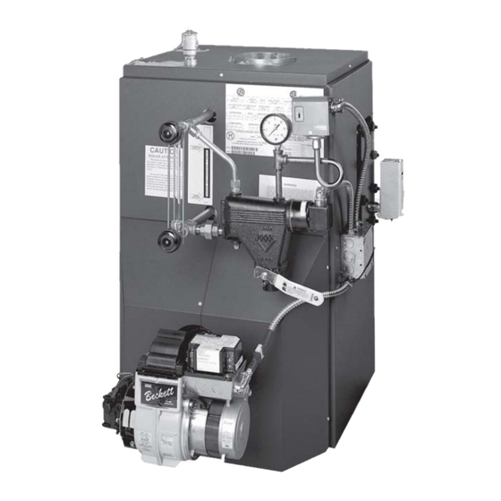
KEYSTONE STEAM II
OIL-FIRED CAST IRON BOILER
MODEL NUMBERS:
KSB0365, KSB3100,
KSB4125, KSB4150,
KSB5175, KSB5200,
KSB6225, KSB7275
PENNCO BOILERS
85 Middle Rd.
Dunkirk, NY 14048
Ph: (716) 366-5500
Fax: (716) 366-1209
An ISO 9001-2000 Certified Company
www.ecrinternational.com
P/N 1305030, Rev. 1.0 [08/04]
Advertisement
Table of Contents

Subscribe to Our Youtube Channel
Related Manuals for PENNCO KEYSTONE STEAM II


Summary of Contents for PENNCO KEYSTONE STEAM II
- Page 1 KEYSTONE STEAM II OIL-FIRED CAST IRON BOILER MODEL NUMBERS: KSB0365, KSB3100, KSB4125, KSB4150, KSB5175, KSB5200, KSB6225, KSB7275 PENNCO BOILERS 85 Middle Rd. Dunkirk, NY 14048 Ph: (716) 366-5500 Fax: (716) 366-1209 An ISO 9001-2000 Certified Company www.ecrinternational.com P/N 1305030, Rev. 1.0 [08/04]...
-
Page 2: Table Of Contents
All installations of boilers and venting should be done only by a qualified expert and in WARNING accordance with the appropriate Pennco manual. Installing or venting a boiler or any Indicates a potentially hazardous situation other gas appliance with improper methods... -
Page 3: Ratings, Data, And Dimensions
RATINGS, DATA, AND DIMENSIONS I=B=R Oil Burner Min. Natural Draft D.O.E. (3)(4) I=B=R Net Ratings Boiler Nozzle Pump Chimney Size Input Heating A.F.U.E. Model Furnished Pressure Capacity Rating Steam Sq. Ft. Water Number 140PSIG G.P.H. Round Square Steam KSB0365 0.65 8x8x15 .60 80B KSB3100... -
Page 4: Installation Procedure
INSTALLATION PROCEDURE WARNING Improper installation, adjustment, alteration, service or maintenance can cause injury or property damage. All installations must conform to the requirements of The boiler shall be installed such that the oil ignition the authority having jurisdiction. Such applicable system components are protected from water requirements take precedence over the general (dripping, spraying, rain etc.) during appliance... -
Page 5: Ventilation And Combustion Air
VENTILATION AND COMBUSTION AIR WARNING Air openings to combustion area must not be obstructed. By following the instructions below, adequate combustion air can be maintained. COMBUSTION AIR REQUIREMENTS 4. When air for combustion and room (Minimum Opening Requirement) ventilation is from inside buildings, the Unconfined Area* Confined Area** Outside Combustion Air... - Page 6 C. If horizontal ducts are used, each opening shall have a minimum free area 1 square inch per 2,000 BTU per hour total input rating of all appliances in the enclosed space. (Figure 4) FIGURE 2 B. When communicating with the outdoors by means of vertical ducts, each opening shall have a minimum free area 1 square inch per 4,000 BTU FIGURE 4...
-
Page 7: Connecting Supply And Return Piping Steam
CONNECTING SUPPLY AND RETURN PIPING 1. Suggested piping for steam heating system can 3. See Figure 6 for typical piping for domestic hot be seen in Figure 5. Actual piping may vary based on water heater. system design and local conditions. 4. -
Page 8: Venting System Inspection And Installation
VENTING SYSTEM INSPECTION & INSTALLATION WARNING Connect flue pipe same size as boiler outlet to chimney, sloping upward continuously toward the Boiler is to be vented by natural draft and shall chimney approximately 1/4" per foot. Bolt or screw not be connected into any portion of a joints together to avoid sag. -
Page 9: Electrical Wiring
If tank is more than 20' from the boiler, a two stage An oil line filter and shut-off valve should be installed fuel unit should be installed in place of the single in the suction line. Shut-off valves should be installed stage pump supplied as standard equipment with in both the suction and return lines at the burner for the burner. - Page 10 STEAM WIRING W/MM #67 MECHANICAL LWCO...
-
Page 11: Normal Sequence Of Operation
NORMAL SEQUENCE OF OPERATION On a call for heat, the thermostat will actuate, com- IMPORTANT TO THE INSTALLER - Before putting pleting the circuit to the boiler. In turn, the ignition the boiler in operation, test the mechanical low water systems are activated and ignition will begin. - Page 12 D. Set room thermostat to call for heat, or jump H. Turn “OFF” burner and install pressure gauge thermostat contacts on the boiler control. port on pump. E. Open all oil line valves. I. Start burner again and check oil pressure for 140 lbs.
- Page 13 A. Pressure Control - Remove cover and note pressure 2. Disconnect power cable at factory supplied burner setting. With boiler operating, decrease the setting. electrical disconnect. (Figure 12) When the setting is lower than boiler pressure, the control will open and turn off the boiler. After checking 3.
-
Page 14: Maintenance Procedures
MAINTENANCE PROCEDURES Before seasonal start up it is advisable to have a The venting system should be inspected at the start competent service agency check the boiler for soot of each heating season. Check the vent pipe from and scale in the flues, change oil filter and nozzle, the boiler to the chimney for signs of deterioration by clean the burner and readjust burner input rate to rust or sagging joints. -
Page 15: Replacement Parts List
pressure to build up. Run a temporary connection The free flow of combustion and ventilation air to the from one of the drain valves to a nearby sewer. boiler and boiler room must not be restricted or Connect to a drain valve on the opposite end of the blocked. - Page 16 REPLACEMENT PARTS - CONTROLS AND HARDWARE ITEM PART NO. DESCRIPTION PF05501 Pipe Fit - Nipple ½" x 2" Brass GA-003.00 Gauge Pressure (Steam) GA-004.00 Gauge - Water Level PF-025.01 Pipe Fit Tee ¼" PF-026.05 Pipe Fit Nipple ¼" x 3" WC-011.00 MLWCO #67-CH-3 24 Volt 275-2-3.01...
- Page 17 REPLACEMENT PARTS - HEAT EXCHANGER ITEM PART NO. DESCRIPTION ITEM PART NO. DESCRIPTION 100-5-10.01 Rear Section Rope, Med. Density - 3 Sec. 13.0' #60 Push Nipple - 3 Sec. Rope, Med. Density - 4 Sec. 19.5' MS-006.00 #60 Push Nipple - 4 Sec. Rope, Med.
- Page 18 REPLACEMENT PARTS - JACKETS ITEM PART NO. DESCRIPTION 21522801 Top Panel - 3 Sec. 21522802 Top Panel - 4 Sec. 21522803 Top Panel - 5 Sec. 21522806 Top Panel - 6 Sec. 21522807 Top Panel - 7 Sec. 21521501 Rear Panel 21523101 Right Side Panel - 3 Sec.
- Page 19 REPLACEMENT PARTS - BURNER COMPONENTS ITEM PART NO. DESCRIPTION BN04002 Burner Oil UT902 Beckett (KSB3100) BN04003 Burner Oil UT903 Beckett (KSB4125) BN04004 Burner Oil UT904 Beckett (KSB4150) BN04006 Burner Oil UT906 Beckett (KSB5200) BN08901 Burner Oil UT1801 Beckett (KSB6225, KSB7275) 30A064202 Burner Oil Riello 40/F5 (KSB3100, KSB4125, KSB4150) BN07007...
-
Page 20: Service Checklist
SERVICE CHECKLIST Inspect Chimney and Flue Pipe [ X ] Inspect and Clean Appliance [ X ] Inspect Oil Line - Size/Leaks [ X ] Inspect Electrical Connections [ X ] Install New Filter [ X ] Room Make-up Air [ X ] Electrode Setting [ X ]...
Need help?
Do you have a question about the KEYSTONE STEAM II and is the answer not in the manual?
Questions and answers