Table of Contents
Advertisement
Models
15B045FE
15B070FE
15B096FE
15B120FE
15B145FE
15B170FE
15B195FE
15B245FE
15B295FE
For Natural Gas Or Propane
An ISO 9001-2008 Certified Company
C.S.A. Certified
Tested For 100 psi
Working Pressure
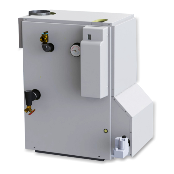
15B SERIES
Cast Iron Gas Fired Boilers
For Forced Hot Water
INSTALLATION, OPERATION &
MAINTENANCE MANUAL
ASME
II
Manufactured by:
ECR International, Inc.
2201 Dwyer Avenue,
Utica NY 13501
web site: www.ecrinternational.com
P/N 240009024, Rev. D [10/2014]
Advertisement
Table of Contents


Need help?
Do you have a question about the 15B II Series and is the answer not in the manual?
Questions and answers