Table of Contents
Advertisement
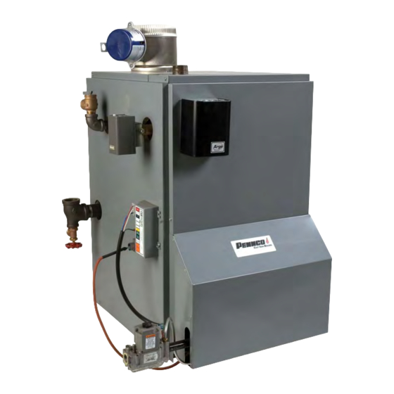
SERIES 15B CAST iRON GAS FIRED BOILERS
MODEL NUMBERS:
15045,15070,15096,
15120,15145,15175,
15195,15245,15295
FOR FORCED HOT WATER
PENNCO BOILERS
85 Middle Rd.
Dunkirk. NY 14048
Ph: (7161 366-5500
Fax: (7161 366-1209
www. ecrinternational.com
R International
Brand
Ic_/
An/SO
9001-2000 Certified Company
F N 1305026, Rev. 1.1 [03/05]
Advertisement
Table of Contents

Related Manuals for PENNCO 15045


Summary of Contents for PENNCO 15045
- Page 1 SERIES 15B CAST iRON GAS FIRED BOILERS FOR FORCED HOT WATER MODEL NUMBERS: 15045,15070,15096, 15120,15145,15175, 15195,15245,15295 PENNCO BOILERS 85 Middle Rd. Dunkirk. NY 14048 Ph: (7161 366-5500 R International Brand Ic_/ Fax: (7161 366-1209 An/SO 9001-2000 Certified Company www. ecrinternational.com...
- Page 2 Pennco hich, if not avoided, WiLL result in death or I manual. Installing or venting a boiler or any other gas appliance...
- Page 3 15045 45,000 37,000 32,000 15070 70,000 57,000 50,000 15096 96,000 79,000 69,000 15120 120,000 98,000 85,000 15145 145,000 119,000 I03,000 15175 175,000 141,000 I23,000 80.5% 15195 195,000 157,000 137,000 80.5% 15245 245,000 197,000 171,000 1,t89 80.5% 15295 295,000 237,000 206,000 1,368 I0.4...
- Page 4 1. The installation must conform to the requirements 7. Allow 24 inches at the front and right side for of the authority having jurisdiction or, in the absence servicing and cleaning. of such requirements, to the latest revision of the National Fuel Gas Code, ANSI Z223.
- Page 5 ,ii!o iiiB is any doubt, install air supply provisions accordance with the latest revision of the National Fuel Gas Code. 15045 3. When a boiler is installed in an unconfined 15070 space in a building unusually tight 15096...
- Page 6 the other within 12 inches from the bottom 3. If horizontal ducts are used, each opening and duct shall have a minimum free area 1 the enclosure. The openings shall communicate directly, or by ducts, with the outdoors or spaces square inch per 2,000 BTU per hour of total (crawl or attic) that freely communicate...
- Page 7 5. Hot water boilers and system must be filled with MPORTANT: Circulators in the foltowing"_ water and maintained to a minimum pressure of 12 tustrations are mounted on the system supply pounds per square inch. ide, but mounting on the system return side is I !so accep!ab!e...
- Page 8 MIXING VALVE PIPING PRIMARY SECONDARY PIPING WITH BYPASS TE_IPERATURE a£uaE C_RCU_£TC,_ _LC, W S,STEr4 V£LVE , T=_,IPE_£TURE S,sUC_= S_ST_4 P ESSdRE =r,ESSURE ,_LVE R_DUO O _EDU,S,r_a "/AL_'E VA:, _L,'E GATE ,h,ALVE ,_L', V£LVE PURaE PURGE [ FIGURE 7] FIGURE 8 ] BOILER INSTALLATION WITH CIRCULATORS >...
- Page 9 II installations of boilers and venting should be done only by a qualified expert and in accordance ith the appropriate Utica Boilers manual. Installing or venting a boiler or any other gas appliance ith improper methods or materials may result in serious injury or death due to fire otto asphyxiation om poisonous gases such as carbon...
- Page 10 E. Test for spitlage atthe draft hood retief opening G. Any improper operation of the common vent- after 5 minutes of main burner operation. ing system should be corrected so the installation conforms with the latest revision of the National the flame of a match or candle, or smoke from a cigarette, cigar or pipe.
- Page 11 1. Connectgas servicefrom meter to control as- 2. The gas line should be of adequate size to prevent semblyin accordancewith ANSIZ223.1 and local undue pressure drop and neversmalter than the pipe codesor utility.A groundjoint unionshould be in- size of the main gas control valve. (See Chart) stalledforeasyremovalofgas controlforservicing.
- Page 12 HONEYWELL L4080B THERMOSTAT --1_ vtA E CAMPER CONTROL BOARD NEUTRAL POWER SUPPLY OVER CURRENT & PROTECTED DESCONNECT...
- Page 13 HONEYWELL LB/C2 L4OSOB v 1 V_aR2°4 THERMOSTAT _>_P L]'_]rJ vR°3°° TH--2 --4< --X< <4 --<4 L_b__ FUSE S8600(F,M) _oo. INTERMITTENT PILOT CONTROL 11234 RSX4 RToT_I_K SSb4 IBK _09_TO PILOT POWER NEUTRAL 115 SUPPLY OVER CURRENT & PROTECTED | | J w l_ wl,u: GAS VALVE DISCONNECT...
- Page 14 push in or turn by hand, don't try to repair it. Call a qualified service technician. Force or attempted repair may result in a fire or explosion. D. Do not use this appliance if any part has been under water. Immediately call a qualified service...
- Page 15 6. Wait (5) minutes to clear out any gas. If you then smell gas, STOP! Follow "What To Do If You Smell Gas" in the safety information above. If you don't smell gas, go on to the next step. 1. STOP! Read the safety information at the beginning of these instructions.
- Page 16 FOR h,/O DE L3: completing the circuit to the control. The completed FOR MODELS: 15045 THROUGH 1509_ i5123 THRCL, GH 15275 circuit to the control will first activate the circulator "\ and damper which will close an end switch inside "\\BLOCKED...
- Page 17 This should be oiled at the same time for quiet boiler components to their original position. operation. Follow the manufacturer's instructions boiler putty or IS-808 GE silicone (available from a oiling the shaft bearing. Pennco distributor) to seal around the flue collector and boiler castings.
- Page 18 A visual checkof the mainburnerand pilotflames shouldbe madeat the start of the heatingseason and again in mid-season.The main burner flame shouldhavea weltdefinedinnerblue mantelwith a lighterblue outermantel,Checkthe burnerthroats andbumerorifices f orlintordustobstruction. ( Figures 19 and 20) MAKN :BURNER PZLOT FLAME LIGHT BLUE OUTER MANTEL...
- Page 19 Gas input to the boiler can be adjusted by removing the 1. Pilot: With main burner operating, turn the protective cap on the pressure regulator (Figures 14- pilot gas adjusting screw clockwise 16 on pages 15-16) and turning the screw clockwise until pilot gas is turned off.
- Page 20 Jacket Front Lower 3raft Hood Pipe Nipple Control Restrictor Pilot Spark Control Jacket Back Jacket Front Upper Therattimeter Gauge Jacket Side Right Right End Section High Limit Control Left End Section Jacket Side Left Pipe Bushing Relief Valve ¢7elt Push Nipple Jacket Top Dipe Nipple Tray...
- Page 21 iiii:!i t!!iN:o:iiii: 3urner Tube 1¾" (045) VG-006.00 Internal Bushing ¾ x ½ (ALL LP) 3urner Tube 1¾" (070, 096) 356-2-1.01 Manifold (045) 3urner Tube 1¾" (120, 145) 3352401 356-2-1.02 Manifold (070, 096) 3urner Tube 1¾" (175, 195) 356-2-1.03 Manifold (120, 145) 3urner Tube 1¾"...
- Page 22 HW06901 18 Wislock 100-2-2.01 B - Left Hand Section _lut 5/16- 14605001 Tie Rod - ¼" x 7¼" (045) Push Nipple 2" Mach. (045) HW-011.01 Tie Rod - ¼"x 11½" (070,096) Push Nipple 2" Mach. (070,096) HW-011.03 Tie Rod - ¼"x 15½" (120, 145) Push Nipple 2"...
- Page 23 1182004 _-"Damper (045) 34620501 =lue Collector (045) 1182005 5" Damper (070,096) 34620502 =lue Collector (070,096) 34620503 =lue Collector (120, I45) 1182006 3" Damper (120, 145) 34620504 =lue Collector (175, 195) 1182007 7" Damper (175, 195) 34620505 =lue Collector (245) 1182008 5"...
- Page 24 1520001 I-hermocouple Q309A 14695046 _crew #8 - I8 x ½ 2380002 (it, Pilot Tube Assy., Nat. Stdg. 20½" 2380006 iKit, Pilot Tube Assy., LP Stdg. 20½" 32621101 Pilot Bracket 3261401 Pilot Shield N/A* iPtot Tube ¼" x 20½" AL * Included with #3 - Pilot Tube Assembly Kit (above) PB00702 Pilot Ignition Cable 30"...
- Page 25 AQ-020.01 Welt ¾" x 3" 1516001 _ipe-Tee1W'x_A'x1W AQ-022.01 High Limit Control PB00702 _ilot Ignition Cable 30" 1310001 Pipe - Nipple _A *'x 4" 375-1-14.01 Wire - Low Voltage/Damper VR-001.01 Relief Valve 30# 37413602 Harness - Ignition to Gas Valve 18" 1190001 Pipe - Elbow _A *' 90 °...
- Page 26 5501270 Kit, C onversion LP toNatural 5501271 Kit, C onversion, LP toNatural I507C 5501272 Kit, C onversion, LP toNatural I509C 5501273 Kit, C onversion, LP toNatural I512C 5501274 Kit, C onversion, LP toNatural 1514_ 5501275 Kit, C onversion, LP toNatural 1517_ 5501276 Kit, Conversion,...
Need help?
Do you have a question about the 15045 and is the answer not in the manual?
Questions and answers