Table of Contents
Advertisement
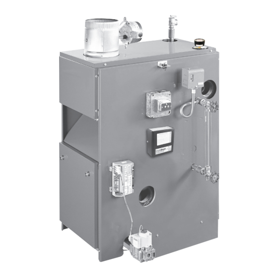
16 Series
GAS-FIRED
STEAM BOILERS
MODELS
INSTALLATION, OPERATION &
1603HSID
MAINTENANCE MANUAL
1604HSID
1605HSID
1606HSID
1607HSID
1608HSID
1609HSID
MODEL HSID
Electronic
Intermittent
Ignition
PENNCO BOILERS
2201 Dwyer Avenue, Utica NY 13501
web site: www.ecrinternational.com
P/N 1305004, Rev. D [08/03/2015]
Advertisement
Table of Contents


Need help?
Do you have a question about the 1603HSID and is the answer not in the manual?
Questions and answers
How to correct error #65