Table of Contents
Advertisement
Available languages
Available languages
Quick Links
Owner's Manual
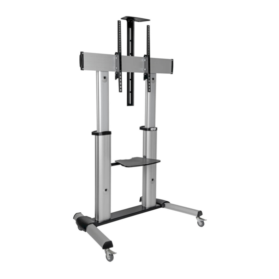
Heavy-Duty Mobile
Flat-Panel Floor Stand
Model: DMCS60100XX
Español 13 • Français 25 • Русский 37 • Deutsch 49
CAUTION: DO NOT EXCEED MAXIMUM LISTED WEIGHT CAPACITY. SERIOUS INJURY OR
PROPERTY DAMAGE MAY OCCUR!
200 x 200 / 300 x 300 /
400 x 200 / 400 x 400 /
600 x 400 / 800 x 400 /
800 x 600 / 1000 x 600
WARRANTY REGISTRATION
automatically entered to win an ISOBAR
1111 W. 35th Street, Chicago, IL 60609 USA • tripplite.com/support
Copyright © 2021 Tripp Lite. All rights reserved.
100"
220 lb.
220 lb.
MAX
(100 kg)
(100 kg)
Register your product today and be
surge protector in our monthly drawing!
tripplite.com/warranty
1
TV
TV
DVD
DVD
11 lb.
11 lb.
(5 kg)
(5 kg)
MAX
MAX
MAX
MAX
®
CAMERA
CAMERA
11 lb.
11 lb.
(5 kg)
(5 kg)
MAX
MAX
Advertisement
Table of Contents

Related Manuals for Tripp Lite DMCS60100XX


Summary of Contents for Tripp Lite DMCS60100XX
- Page 1 WARRANTY REGISTRATION Register your product today and be automatically entered to win an ISOBAR ® surge protector in our monthly drawing! tripplite.com/warranty 1111 W. 35th Street, Chicago, IL 60609 USA • tripplite.com/support Copyright © 2021 Tripp Lite. All rights reserved.
-
Page 2: Warranty And Product Registration
FREE Tripp Lite product!* * No purchase necessary. Void where prohibited. Some restrictions apply. See website for details. Tripp Lite has a policy of continuous improvement. Specifications are subject to change without notice. Photos and illustrations may differ slightly from actual products. -
Page 3: Component Checklist
Component Checklist IMPORTANT: Ensure that you have received all parts according to the component checklist prior to installing. If any parts are missing or faulty, visit www.tripplite.com/support for service. Middle Base (x1) Left Leg (x1) Right Leg (x1) Left Cover (x1) Right Cover (x1) Universal Plate (x1) Plastic Handle (x2) -
Page 4: Assemble The Base
1. Assemble the Base Middle Base Left Leg M6x16 Caster Right Leg Hex Key Wrench Never Overtighten • Insert the right leg into the base. Align the holes in the right leg to the holes in the base. Secure with the screws. Repeat this step for the left Screws leg. - Page 5 3. Attach Columns to Base During this step, the columns are not secured to the base with screws. Be careful not to knock the columns over. Plastic Handle Right Column Left Column...
- Page 6 4. Attach Universal Plate to Columns M6x14 Universal Plate Universal Plate Support Insert the Universal Plate’s Supports into the column along the column rails. Tighten all screws with a suitable Philips screwdriver. Top Cover 5. Secure Columns to Base Using the Hex Key, tighten the screws to secure the columns to the base.
- Page 7 5. Secure Columns to Base Tighten the safety screws. M6x25 Philips Rounded Head 6. Assemble the DVD Shelf Knob M6x25 Hex Rounded Head M6x14 Support Bar...
- Page 8 7. Attach DVD Shelf to Columns Support Block M6x25 Hex Socket Head Hex Key Hex Key Use the Hex Key and screws to secure the DVD Adjust the Columns to the desired height before Shelf Assembly to the Columns’ Support Blocks. installing the display.
- Page 9 8. Attach Adapter Brackets to Display 8.2 For Recessed-Back Screens or Access to A/V Inputs M6x30 M8x30 Washer Do not over-tighten Small screws. Spacer M6x30 M8x30 Washer Spacer M6x30 M8x30 M8x50 M8x50 M8x50 Washer Washer Washer Washer Small Small Small Spacer Spacer Spacer...
-
Page 10: Cable Management
10. Cable Management Route the power and connection cables through the openings on the Left and Right Columns. 11. Assemble the Camera Shelf M4x6 Camera Shelf M4x6 Connecting Plate Use a Philips screwdriver and screws to attach the Camera Shelf to the Connecting Plate. - Page 11 12. Attach the Camera Shelf Assembly to the Universal Plate Remove Screws Insert Removed Screws to attach Connecting Plate Remove the Universal Plate’s two rear screws, then attach the Camera Shelf Assembly using the same screws just removed. Adjust the Camera Shelf Assembly to the desired height, then secure by tightening the screws with a Philips screwdriver.
-
Page 12: Maintenance
13. Adjustment +5° –10° 1200 mm 1250 mm 1300 mm 1350 mm 1400 mm 1450 mm 1500 mm TV panel center 1550 mm height measured 1600 mm from floor. 1650 mm Use the Hex Key to loosen the screws on Support Block both support blocks. -
Page 13: Manual Del Propietario
5 kg 5 kg 5 kg 5 kg 800 x 600 / 1000 x 600 MÁXIMO MÁXIMO MÁXIMO MÁXIMO MÁXIMO MÁXIMO 1111 W. 35th Street, Chicago, IL 60609 EE. UU. • tripplite.com/support Copyright © 2021 Tripp Lite. Todos los derechos reservados. - Page 14 Ya que las aplicaciones individuales están sujetas a gran variación, el fabricante no garantiza la adecuación de estos dispositivos para alguna aplicación específica. Tripp Lite tiene una política de mejora continua. Las especificaciones están sujetas a cambio sin previo aviso. Las fotografías e ilustraciones pueden diferir ligeramente de los productos reales.
- Page 15 Accesorios y Partes Incluidas en el Empaque IMPORTANTE: Asegúrese de haber recibido todas las partes de acuerdo a la lista de comprobación de componentes antes de instalar. Si faltase cualquier parte o estuviese dañada, visite www.tripplite.com/support para solicitar servicio. Base Central (x1) Pata Izquierda Pata Derecha Cubierta Izquierda...
- Page 16 1. Ensamble de la Base Base Central Pata Izquierda M6x16 Rueda Pata Derecha Llave Hexagonal Llave Nunca Apriete los • Inserte la pata derecha en la base. Alinee los orificios en la pata derecha con los orificios en la base. Asegure con los tornillos. Repita este paso Tornillos en Exceso para la pata izquierda.
- Page 17 3. Fije las Columnas a la Base Durante este paso, las columnas no se sujetan a la base con tornillos. Tenga cuidado de no dejar caer las columnas. Manija de Plástico Columna Derecha Columna Izquierda...
- Page 18 4. Coloque la placa Universal en las Columnas M6x14 Soporte para Placa Placa Universal Universal Inserte los soportes de la Placa Universal en la columna a lo largo de los rieles de la columna. Apriete todos los tornillos con un desatornillador Philips adecuado. Tapa Superior 5.
- Page 19 5. Asegure las Columnas a la Base Apriete los tornillos de seguridad. M6x25 Philips de Cabeza Redonda 6. Ensamble la Repisa para DVD Perilla Allen de Cabeza Redonda M6x25 M6x14 Barra de Soporte...
- Page 20 7. Fije la Repisa para DVD a las columnas Bloque de Soporte Llave Hexagonal Tornillos Allen de Cabeza Hueca M6x25 Llave Hexagonal Llave Hexagonal Utilice la llave y tornillos Allen para fijar al Ajuste las columnas a la altura deseada antes de Conjunto de Repisa de DVD a los Bloques de instalar la pantalla.
- Page 21 8. Fije los Soportes del Adaptador a la Pantalla Para Pantalla con Respaldo Cóncavo o para Acceder a Entradas de Audio y Video M6x30 M8x30 Arandela No apriete excesivamente los tornillos Espaciador Pequeño M6x30 M8x30 Arandela Espaciador Grande M6x30 Espaciador M8x30 M8x50 M8x50...
- Page 22 10. Administración del Cableado Conduzca los cables de alimentación y conexión a través de las aberturas de las Columnas Izquierda y Derecha. 11. Ensamble la Repisa para Cámara M4x6 Repisa para M4x6 Cámara Placa de Conexión Utilice un desatornillador y tornillos Philips para fijar la Repisa para Cámara a la placa de conexión.
- Page 23 12. Fije el Conjunto de Repisa para Cámara a la Placa Universal Retire los Tornillos Inserte los tornillos retirados para colocar la placa de conexión Retire los dos tornillos traseros de la placa Universal, entonces sujete al Conjunto de Repisa para Cámara utilizando los mismos tornillos que retiró.
-
Page 24: Mantenimiento
13. Ajuste +5° –10° 1200 mm 1250 mm 1300 mm 1350 mm 1400 mm 1450 mm 1500 mm Altura del centro del panel 1550 mm de TV medida 1600 mm desde el piso. 1650 mm Utilice la llave Bloque de Soporte hexagonal para aflojar los tornillos en ambos bloques... -
Page 25: Manuel De L'utilisateur
(11 lb) (11 lb) (11 lb) (11 lb) 800 x 600 / 1 000 x 600 MAX. MAX. MAX. MAX. MAX. MAX. 1111 W. 35th Street, Chicago, IL 60609 USA • tripplite.com/support Droits d'auteur © 2021 Tripp Lite. Tous droits réservés. -
Page 26: Garantie
à l'aptitude ou l'adaptation de ces dispositifs pour une application spécifique. La politique de Tripp Lite en est une d’amélioration continue. Les spécifications sont sujettes à changement sans préavis. Les produits réels peuvent différer légèrement des photos et des illustrations. - Page 27 Liste de vérification des composants IMPORTANT : S'assurer d'avoir reçu toutes les pièces conformément à la liste de vérification des composants avant de procéder à l'installation. Si des pièces sont manquantes ou défectueuses, visiter www.tripplite.com/support pour obtenir de l'aide. Base du milieu Patte gauche Patte droite Couvercle gauche...
- Page 28 1. Assemblage de la base Base du milieu Patte gauche M6x16 Roulette Patte droite Clé hexagonale Clé Ne jamais trop • Insérer la patte droite dans la base. Aligner les trous dans la patte droite serrer les vis. avec les trous dans la base. Fixer en utilisant les vis. Répéter cette étape pour la patte gauche.
- Page 29 3. Fixer les colonnes à la base. Pendant cette étape, les colonnes ne sont pas fixées à la base avec des vis. Prendre garde de ne pas renverser les colonnes. Poignée en plastique Colonne de droite Colonne de gauche...
- Page 30 4. Fixer la plaque universelle aux colonnes. M6x14 Support de la plaque Plaque universelle universelle Insérer les supports de la plaque universelle dans la colonne le long des rails des colonnes. Serrer toutes les vis avec un tournevis Philips approprié. Couvercle supérieur 5.
- Page 31 5. Fixer les colonnes à la base. Serrer les vis de sûreté. Tête ronde Philips M6x25 6. Assembler l'étagère pour DVD. Bouton Tête ronde hexagonale M6x25 M6x14 Barre de support...
- Page 32 7. Fixer l'étagère pour DVD aux colonnes. Clé Bloc de support hexa- gonale Tête creuse hexagonale M6x25 Clé hexagonale Clé hexagonale Ajuster les colonnes à la hauteur désirée avant Utiliser la clé hexagonale et les vis pour fixer d'installer l'écran. l'ensemble de l'étagère pour DVD aux blocs de support des colonnes.
- Page 33 8. Fixer les supports d'adaptateur à l'écran. 8.2 Pour les écrans à dos encastré ou les entrées d'accès A/V M6x30 M8x30 Rondelle Ne pas trop serrer Petite les vis. entretoise M6x30 M8x30 Rondelle Grande entretoise M6x30 Grande M8x30 M8x50 entretoise M8x50 M8x50 Rondelle...
-
Page 34: Gestion Des Câbles
10. Gestion des câbles Acheminer les câbles d'alimentation et de raccordement à travers les ouvertures sur les colonnes de gauche et de droite. 11. Assembler l'étagère pour caméra. M4x6 Étagère pour M4x6 caméra Plaque de connexion Utiliser un tournevis et des vis Philips pour fixer l'étagère pour caméra à... - Page 35 12. Fixer l'ensemble de l'étagère pour caméra à la plaque universelle. Enlevez les vis. Insérer les vis retirées pour fixer la plaque de connexion. Retirer les deux vis arrière de la plaque universelle, puis fixer l'ensemble de l'étagère pour caméra en utilisant les vis venant tout juste d'être retirées.
-
Page 36: Entretien
13. Réglage +5° –10° 1 200 mm 1 250 mm 1 300 mm 1 350 mm 1 400 mm 1 450 mm 1 500 mm Hauteur du centre du 1 550 mm panneau de télévision 1 600 mm mesurée depuis le plancher. 1 650 mm Utiliser la clé... -
Page 37: Руководство Пользователя
ДО ДО 800 x 600 / 1000 x 600 100 кг 100 кг 5 кг 5 кг 5 кг 5 кг 1111 W. 35th Street, Chicago, IL 60609 USA • tripplite.com/support Охраняется авторским правом © 2021 Tripp Lite. Перепечатка запрещается. - Page 38 заверений или гарантий относительно пригодности данных изделий для какого-либо конкретного применения или их соответствия каким-либо конкретным требованиям. Компания Tripp Lite постоянно совершенствует свою продукцию. В связи с этим возможно изменение технических характеристик без предварительного уведомления. Внешний вид реальных изделий может несколько отличаться от представленного на фотографиях и иллюстрациях.
- Page 39 Перечень комплектации ВНИМАНИЕ! Перед началом установки убедитесь в том, что вами получены все детали согласно перечню комплектации. В случае отсутствия или повреждения каких-либо деталей обратитесь за помощью на страницу www.tripplite.com/support. Среднее основание (1 шт.) Левая ножка Правая ножка (1 шт.) Левая...
- Page 40 1. Сборка основания Среднее основание Левая ножка M6x16 Ролик Правая ножка Шестигранный ключ Гаечный ключ • Вставьте правую ножку в основание. Совместите отверстия в правой ножке с отверстиями в Ни в коем случае не основании. Зафиксируйте соединения винтами. Повторите указанные действия для левой ножки. перетягивайте...
- Page 41 3. Крепление опорных стоек к основанию При выполнении этого действия опорные стойки не прикреплены к основанию винтами. Внимательно следите за тем, чтобы не сбить опорные стойки. Пластмассовая ручка Правая опорная стойка Левая опорная стойка...
- Page 42 4. Крепление универсальной пластины к опорным стойкам M6x14 Опорный Универсальная кронштейн пластина универсальной пластины Вставьте кронштейны универсальной пластины в опорные стойки вдоль направляющих. Затяните все винты с помощью крестообразной отвертки соответствующего размера. Верхняя заглушка 5. Крепление опорных стоек к основанию С...
- Page 43 5. Крепление опорных стоек к основанию Затяните предохранительные винты. Винт M6x25 с цилиндрической головкой и крестообразным шлицем 6. Сборка полки для DVD-проигрывателя Фиксирующая гайка Винт M6x25 со сферической головкой под шестигранник M6x14 Опорная рейка...
- Page 44 7. Крепление полки для DVD-проигрывателя к опорным стойкам Опорный блок Шестиг- ранный ключ Винт M6x25 с внутренним шестигранником Шестигранный ключ Шестигранный ключ Прикрепите собранную полку для DVD-проигрывателя винтами к Перед установкой дисплея отрегулируйте высоту опорных стоек. опорным блокам стоек при помощи шестигранного ключа. 8.
- Page 45 8. Крепление переходных кронштейнов к дисплею 8.2 Для экранов, устанавливаемых заподлицо, или для получения доступа к разъемам аудио-/видеовхода M6x30 M8x30 Шайба Не перетягивайте винты. Малая проставка или M6x30 M8x30 Шайба Большая проставка M6x30 M8x30 или M8x50 M8x50 M8x50 Шайба Шайба Шайба...
- Page 46 10. Оптимизация кабельных соединений Протяните кабели питания и соединительные кабели через отверстия в левой и правой опорных стойках. 11. Сборка полки для камеры M4x6 Полка для камеры M4x6 Соединительная пластина Прикрепите полку для камеры винтами к соединительной пластине с помощью крестообразной...
- Page 47 12. Крепление собранной полки для камеры к универсальной пластине Выверните винты Вставьте вывернутые винты для крепления соединительной пластины Выверните два задних винта универсальной пластины, а затем прикрепите собранную полку для камеры, используя только что вывернутые винты. Отрегулируйте высоту полки для камеры и зафиксируйте ее на нужной высоте, затянув винты с помощью крестообразной отвертки.
- Page 48 13. Регулировка +5° –10° 1200 мм 1250 мм 1300 мм 1350 мм 1400 мм 1450 мм 1500 мм Высота центра 1550 мм ТВ-панели 1600 мм над полом. 1650 мм Ослабьте винты на обоих опорных блоках с помощью Опорный блок шестигранного ключа. Отрегулируйте...
- Page 49 (100 kg) (5 kg) (5 kg) (5 kg) (5 kg) 800 x 600 / 1000 x 600 max. max. max. max. max. max. 1111 W. 35th Street, Chicago, IL 60609 USA • tripplite.com/support Copyright © 2021 Tripp Lite. Alle Rechte vorbehalten.
- Page 50 Einsatz sicher ist. Da die Anwendungen variieren können, übernimmt der Hersteller keine Garantie bezüglich der Eignung dieser Geräte für einen bestimmten Verwendungszweck. Tripp Lite hat den Grundsatz, sich kontinuierlich zu verbessern. Spezifikationen können ohne Ankündigung geändert werden. Fotos und Illustrationen können von den tatsächlichen Produkten leicht abweichen.
- Page 51 Komponentenliste WICHTIG: Überprüfen Sie, ob Sie alle in der Komponentenliste aufgeführten Teile erhalten haben, bevor Sie mit der Installation beginnen. Wenn Teile beschädigt oder nicht vorhanden sind, besuchen Sie bitte www.tripplite.com/support. Mittelsockel (1 x) Fuß links Fuß rechts (1 x) Abdeckung links Abdeckung rechts (1 x)
- Page 52 1. Montage des Sockels Mittelsockel Fuß links M6x16 Laufrolle Fuß rechts Inbusschlüssel Schraubenschlüssel Ziehen Sie die • Setzen Sie den rechten Fuß in den Sockel ein. Richten Sie die Löcher im Schrauben nicht zu rechten Fuß an den Löchern im Sockel aus. Sichern Sie beides mit den fest an Schrauben.
- Page 53 3. Montage der Säulen am Sockel Bei diesem Schritt sind die Säulen nicht mit Schrauben am Sockel befestigt. Achten Sie darauf, die Säulen nicht umzuwerfen. Kunststoffgriff Säule rechts Säule links...
- Page 54 4. Befestigen der Universalplatte an den Säulen M6x14 Stütze der Universalplatte Universalplatte Setzen Sie die Stützen der Universalplatte an den Säulenschienen in die Säulen ein. Ziehen Sie alle Schrauben mit einem passenden Kreuzschlitzschraubendreher fest. Abdeckung oben 5. Montage der Säulen am Sockel Um die Säulen am Sockel zu befestigen, ziehen Sie die Schrauben mit dem...
- Page 55 5. Montage der Säulen am Sockel Ziehen Sie die Sicherheitsschrauben fest. Kreuzschlitz-Linsenschraube M6x25 6. Montage des DVD-Regals Griff Sechskant-Linsenschraube M6x25 M6x14 Haltevorrichtung...
- Page 56 7. Befestigen des DVD-Regals an den Säulen Stützblock Inbus- schlüssel Sechskant- Zylinderschraube M6x25 Inbusschlüssel Inbusschlüssel Stellen Sie die Säulen auf die gewünschte Höhe ein, Nutzen Sie den Inbusschlüssel und die bevor Sie den Bildschirm anbringen. Sechskantschrauben, um das montierte DVD-Regal an den Haltevorrichtungen der Säulen zu befestigen.
- Page 57 8. Befestigen der Adapterhalterungen am Bildschirm 8.2 Für Bildschirme mit vertiefter Rückseite oder Zugriff auf A/V-Eingänge M6x30 M8x30 Beilagscheibe Ziehen Sie die Schrauben nicht zu fest an. Kleiner Abstandhalter oder M6x30 M8x30 Beilagscheibe Großer Abstandhalter M6x30 M8x30 oder M8x50 M8x50 M8x50 Beilagscheibe Beilagscheibe...
- Page 58 10. Kabelführung Fühlen Sie die Strom- und Anschlusskabel durch die Öffnungen an der rechten und der linken Säule. 11. Montage des Kameraregals M4x6 Kameraregal M4x6 Verbindungsplatte Nutzen Sie einen Kreuzschlitzschraubendreher und passende Schrauben, um das Kameraregal an der Verbindungsplatte zu befestigen.
- Page 59 12. Befestigen des montierten Kameraregals an der Universalplatte Entfernen Sie die Schrauben. Entfernte Schrauben einsetzen, um die Verbindungsplatte zu befestigen. Entfernen Sie die beiden hinteren Schrauben der Universalplatte und befestigen Sie dann das montierte Kameraregal mit den beiden gerade entfernten Schrauben. Stellen Sie das montierte Kameraregal auf die gewünschte Höhe ein, sichern Sie es dann, indem Sie die Schrauben mit einem Kreuzschlitzschraubendreher festziehen.
- Page 60 13. Einstellen +5° -10° 1200 mm 1250 mm 1300 mm 1350 mm 1400 mm 1450 mm 1500 mm Mitte des TV-Panels, 1550 mm Höhe vom Fußboden 1600 mm gemessen. 1650 mm Nutzen Sie den Inbusschlüssel, um die Schrauben an Stützblock beiden Stützblöcken zu lösen.
Need help?
Do you have a question about the DMCS60100XX and is the answer not in the manual?
Questions and answers