
Subscribe to Our Youtube Channel
Related Manuals for K2 Systems Splice Foot X

Summary of Contents for K2 Systems Splice Foot X
- Page 1 We support PV systems Formerly Everest Solar Systems Splice Foot X & XL Patent Pending QUICK GUIDE k2-systems.com...
- Page 2 Important Note The Splice Foot X & XL can be installed as rafter attached or deck attached. Rafter attached requires that two screws be installed into the rafters using the center holes on the Splice Foot base. Deck attached...
- Page 3 Assembly Corner out and mark array on roof. Snap chalk lines for rail location within shingle course. (Refer to module manufacturer frame clamping zones). Mark mounting locations over rafters and chalk lines within shingle course. Refer to engineering letters for allowable mount spacing. Mount Placement and Installation (Rafter Connection) Locate the rafter and clean roofing surface for mount placement.
- Page 4 Mount Placement and Installation (Deck Connection) For deck attachments, follow steps in 2a, but only use Splice Foot screws in the four corners of the mount. When possible always attach mounts to the rafter and only use deck attached as a secondary option when rafters are not within mounting zones for the array.
- Page 5 Sealant application Apply appropriate sealant to top and each side edge of mount, covering exposed butyl. No need to apply to the bottom of mount. If the mount falls on top of a shingle seam, fill and seal the seam with a compatible roof sealant.
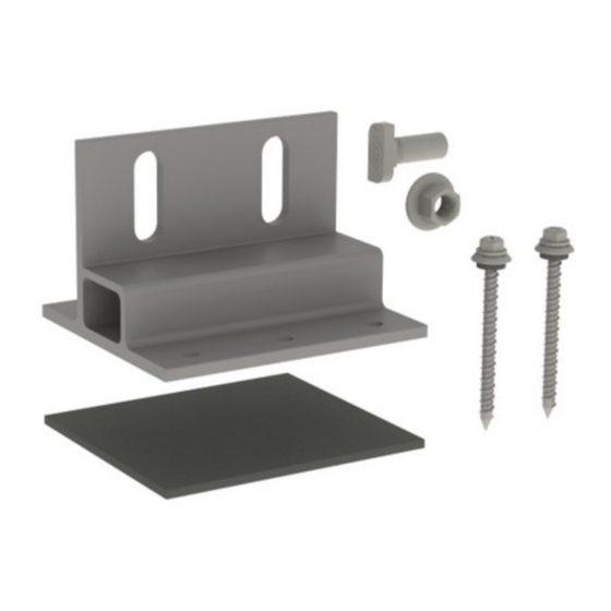
- Page 6 Splicing two rails When connecting two rails to the Splice Foot, insert two T-Bolts through the Splice Foot slots and into side channel of CrossRail. Turn the T-Bolts clockwise ensuring that the mark at the end of the shaft is vertical, indicating proper alignment.
Need help?
Do you have a question about the Splice Foot X and is the answer not in the manual?
Questions and answers