Advertisement
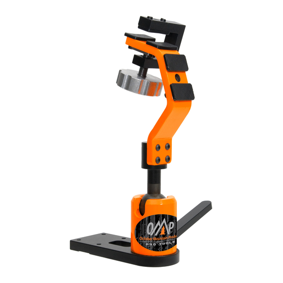
Versa-Cradle Bow Vise
Move or Rotate the Clamping Assembly:
1. Remove the bow and loosen the Tightening Knob (7) almost all the way.
2. Remove the Tightening Knob Shoulder Screw (8) with the 1/8" hex wrench (provided)
while holding the Tightening Knob steady with the other hand.
3. Remove the clamping assembly including the Guide Plate (6) and move the Tightening
Knob Shoulder Screw into the other hole (or rotate it), making sure that the Shoulder
Screw goes in all the way (the head of the screw will be approximately even with the
surface of the Main Beam (1).
4. Move the clamp assembly to the new position and, using the long end of the 1/8" hex
wrench through the hole in the C-Frame, thread the Shoulder Screw into the Tighten-
ing Knob while also positioning the Guide Plate between the four Cushioning Pads (4)
and against the frame.
5. Firmly re-tighten the Tightening Knob Shoulder Screw with the short arm of the hex
wrench in the head of the Shoulder Screw.
Adjust the OMP Versa-Cradle Bow Vise Ball Assembly:
If the Versa-Cradle's handle over rotates against its stop without fully tightening
the ball, loosen the handle as far as it will go, loosen the set screw (Image 1) directly
above the handle half a turn with the 3/32" hex wrench (provided) insert the short
end of the hex wrench into one of the seven holes (Image 2) on the bottom side of the
tightening nut and rotate it in a counterclockwise direction until snug as viewed from
the top side of the Versa-Cradle. Working the handle back and forth a little during this
process can help free the nut and rotate it. Once almost all of the slack is taken out of
the handle, retighten the set screw.
Ball Tension Spring
Ball Tension Spring (10) keeps a constant light tension on the
Handle (3). The Ball Tension Spring can be removed by rotating
the Handle all the way to the tight position, compress the spring
together and pull the spring out. Re-installation is done in reverse.
Image 1
Set Screw
Assembly Instructions
Image 2
4
8
4
2
10
Beam Assembly
Main Beam
1
Main Beam Screws
2
(4, 10-32 x 7/8" Button Head Screws)
Base Screws
3
(4, 10-32 x 3/4" Button Head Screws)
Cushioning Pads
4
C-Frame
5
Guide Plate
6
Tightening Knob Shoulder Screw
7
Shoulder Screw
8
Base Plate
9
Wood Screws
10
7
Case Assembly
1
Case (CNC Machined Steel Case)
Ball (CNC Machined ball with beam post)
2
Handle (Steel handle w/ welded threaded post)
3
Brass Socket (CNC Machined brass ball socket)
4
Clamping Nut (Adjustable)
5
Case Set Screw (1, 10-32 x 3/8" Set Screw)
6
Base (Aluminum machined base for case)
7
Base Screws (4, 10-32 x 3/4" Flat Screws)
8
Retaining Ring (1, 1-1/2" Internal Retaining Ring)
9
Ball Tension Spring
10
4
4
5
6
1
7
9
3
1
6
2
10
4
5
3
9
8
Advertisement
Table of Contents

Related Manuals for OMP Versa


Summary of Contents for OMP Versa
- Page 1 Versa-Cradle. Working the handle back and forth a little during this process can help free the nut and rotate it. Once almost all of the slack is taken out of the handle, retighten the set screw.
- Page 2 & vertical bows! To Mount the Bow Vise: The Versa-Cradle Archery Bow Vise can be mounted using either the four wood screws (provided), or using bolts. (If leather or rubber is used under the base to help protect the finish of fine benches or counter tops, please make sure that it is secure before mounting a bow.)
Need help?
Do you have a question about the Versa and is the answer not in the manual?
Questions and answers