Table of Contents
Advertisement
Quick Links
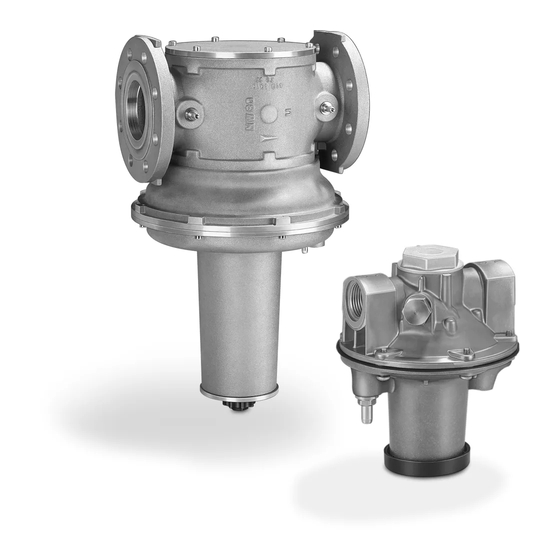
Air/gas ratio controls GIK,
variable air/gas ratio controls GIKH
Contents
1 Safety . . . . . . . . . . . . . . . . . . . . . . . . . . . . . . . . 1
2 Checking the usage . . . . . . . . . . . . . . . . . . . . . 2
3 Installation . . . . . . . . . . . . . . . . . . . . . . . . . . . . 2
4 Installing the air control line. . . . . . . . . . . . . . . . 3
5 Installing the breather line. . . . . . . . . . . . . . . . . 4
6 Tightness test. . . . . . . . . . . . . . . . . . . . . . . . . . 4
7 Setting the low-fire rate. . . . . . . . . . . . . . . . . . . 4
8 Bypass for staged control . . . . . . . . . . . . . . . . 5
9 Installing the variable restrictor . . . . . . . . . . . . . 6
10 Maintenance cycles . . . . . . . . . . . . . . . . . . . . 7
11 Accessories . . . . . . . . . . . . . . . . . . . . . . . . . . 7
12 Technical data . . . . . . . . . . . . . . . . . . . . . . . . 8
13 Designed lifetime . . . . . . . . . . . . . . . . . . . . . . 9
14 Certification . . . . . . . . . . . . . . . . . . . . . . . . . . 9
15 Logistics . . . . . . . . . . . . . . . . . . . . . . . . . . . . 10
oPeRAtInG InstRUCtIons
· Edition 09.21 · EN · 03250312
1 sAFetY
1.1 Please read and keep in a safe place
Please read through these instructions care-
fully before installing or operating. Following the installa-
tion, pass the instructions on to the operator. This unit
must be installed and commissioned in accordance
with the regulations and standards in force. These
instructions can also be found at www.docuthek.com.
1.2 explanation of symbols
1 , 2 , 3 , a , b , c = Action
➔ = Instruction
1.3 Liability
We will not be held liable for damage resulting from
non-observance of the instructions and non-com-
pliant use.
1.4 safety instructions
Information that is relevant for safety is indicated in the
instructions as follows:
DAnGeR
Indicates potentially fatal situations.
WARnInG
Indicates possible danger to life and limb.
CAUtIon
Indicates possible material damage.
All interventions may only be carried out by qualified
gas technicians. Electrical interventions may only be
carried out by qualified electricians.
1.5 Conversion, spare parts
All technical changes are prohibited. Only use OEM
spare parts.
Advertisement
Table of Contents

Related Manuals for Honeywell Kromschröder GIK Series


Summary of Contents for Honeywell Kromschröder GIK Series
-
Page 1: Table Of Contents
Air/gas ratio controls GIK, variable air/gas ratio controls GIKH oPeRAtInG InstRUCtIons · Edition 09.21 · EN · 03250312 1 sAFetY 1.1 Please read and keep in a safe place Please read through these instructions care- fully before installing or operating. Following the installa- tion, pass the instructions on to the operator. -
Page 2: Checking The Usage
GIKH 2 CHeCKInG tHe UsAGe Air/gas ratio controls GIK for maintaining a constant Rp 3/8 gas/air ratio of 1:1 and for gas pressure control in systems without preheated combustion air. Variable air/gas ratio controls GIKH for maintaining Rp 1/2 a constant gas/air ratio of 4:1 and for gas pressure control in systems using a recuperative air preheating system. -
Page 3: Installing The Air Control Line
➔ The regulator must not be in contact with masonry. 4 InstALLInG tHe AIR ContRoL Ensure that there is sufficient space for adjusting LIne the low-fire rate. ➔ Every signal line whose failure may lead to the uncontrolled escape of gas and therefore to an unsafe status and gas fire must be made of metal. -
Page 4: Installing The Breather Line
➔ The cover cap must be removed from the GIK..R 5 InstALLInG tHe BReAtHeR LIne and GIKH for setting the low-fire rate. GIKH ➔ When fitting the unit into a gas line, an Rp 1/2 breather line must be connected, which must be routed to a safe area. -
Page 5: Bypass For Staged Control
Control pressure 8 BYPAss FoR stAGeD ContRoL ➔ GIK..B: the air control pressure must be less than For staged control, the spring is decompressed at the 2 mbar at low-fire rate. factory in such a way that the low-fire rate only flows ➔... -
Page 6: Installing The Variable Restrictor
Installing the variable restrictor on the GIK..R 9 InstALLInG tHe VARIABLe Re- stRICtoR If air control pressure p > inlet pressure p : install a variable restrictor on the GIK. CAUtIon Installing the variable restrictor on the GIK..F Incorrect installation Please observe the following to ensure that the unit is not damaged: –... -
Page 7: Maintenance Cycles
4 Open the air valve fully. 11 ACCessoRIes 5 Adjust it until the air control pressure p reach- sa max. 11.1 Bypass screw GIK 15–25, variable es the calculated value. Observe the gas and air pressures on the downstream consumers. The bore hole diameter for the flow rate can be adjusted as desired and corresponds to holes of 1.5–4 mm, see page 5 (8 Bypass for staged control). -
Page 8: Technical Data
11.3 Conversion kit for zero pressure control 12 teCHnICAL DAtA 12.1 Ambient conditions Icing, condensation and dew in and on the unit are not permitted. Avoid direct sunlight or radiation from red-hot surfaces The zero shut-off prevents an increase in the outlet on the unit. -
Page 9: Designed Lifetime
Housing: AlSi. 14 CeRtIFICAtIon Diaphragms: NBR. Declaration of conformity Bypass screw: brass. GIK 15–25 bypass orifice: standard Ø 1.5 mm, up to Ø 4 mm possible. GIK 40–50 bypass orifice: standard Ø 5 mm, up to Ø 9 mm possible. We, the manufacturer, hereby declare that the prod- GIK 15–50 ucts GIK 15–50 and GIKH 25 with product ID No. -
Page 10: Logistics
Components are to be disposed of separately in ac- cordance with local regulations. FoR MoRe InFoRMAtIon The Honeywell Thermal Solutions family of products includes Honeywell Combustion Safety, Eclipse, Exothermics, Hauck, Kromschröder and Maxon. To learn more about our products, visit ThermalSolutions.honeywell.com or contact your Honeywell Sales...
Need help?
Do you have a question about the Kromschröder GIK Series and is the answer not in the manual?
Questions and answers