
Related Manuals for Abov E-PGM+


Summary of Contents for Abov E-PGM+
- Page 1 E-PGM+ / E-GANG4/6 / E-PGM Serial Programmer User’s Manual Version 1.0.3 Global Top Smart MCU Innovator, ABOV Semiconductor www.abovsemi.com...
-
Page 2: Table Of Contents
Contents E-PGM+ / E-GANG4/6 / E-PGM Serial User’s Manual Contents Introduction ............................ 6 Hardware ............................7 Specifications ........................7 Functions ..........................8 2.2.1 E-PGM+ Programmer ..................... 8 2.2.2 E-PGM Serial Programmer................... 10 2.2.3 E-GANG4/E-GANG6 Programmer ............... 12 Pin Configuration ....................... 15 2.3.1 40-pin DIP TEXTOOL Socket ................ - Page 3 E-PGM+ / E-GANG4/6 / E-PGM Serial User’s Manual List of Figures List of Figures Figure 1. Programmer ..........................6 Figure 2. E-PGM+ with Target Socket Module ..................8 Figure 3. E-PGM+ Top and Side Views for Function Description ............9 Figure 4.
- Page 4 List of Figures E-PGM+ / E-GANG4/6 / E-PGM Serial User’s Manual Figure 49. Example of Multiple Connections of E-PGM+ ..............43 Figure 50. Internal Step-up Power Selection ..................44 Figure 51. Insertion of 200 Ohms in VPP Line ..................45...
- Page 5 E-PGM+ / E-GANG4/6 / E-PGM Serial User’s Manual List of Tables List of Tables Table 1. Programmer Specifications ....................... 7 Table 2. Programmer Functions ......................7 Table 3. Pin Assignment for 40-pin TEXTOOL Socket ................15 Table 4. Connection Table for 10-pin IDC Connector................16 Table 5.
-
Page 6: Introduction
E-PGM+ / E-GANG4/6 / E-PGM Serial User’s Manual Introduction E-PGM+, E-GANG4/6 and E-PGM Serial series are the universal programming equipment for the ABOV Semiconductor’s MCU series, delivering superior performance and reliability. This product line-up has the following features: Fast programming speed for mass manufacturing ... -
Page 7: Hardware
E-PGM+ / E-GANG4/6 / E-PGM Serial User’s Manual 2. Hardware Hardware Specifications The E-PGM+ and E-GANG4/GANG6 have similar features, but the E-PGM Serial has different features. The E-PGM Serial was designed only for On-board Programming purpose and features Noise Robust for the mass production environment. Specifications of each Programmer equipment are compared in Table 1. -
Page 8: Functions
E-PGM+ Programmer The E-PGM+ is a standalone type universal Programmer, which is capable of programming any series of ABOV’s microcontrollers. The E-PGM+ consists of main Programmer equipment and the target device socket and socket adaptor parts. Figure 2. E-PGM+ with Target Socket Module... -
Page 9: Figure 3. E-Pgm+ Top And Side Views For Function Description
E-PGM+ / E-GANG4/6 / E-PGM Serial User’s Manual 2. Hardware Figure 3 and the following list describe external features of the E-PGM+: Figure 3. E-PGM+ Top and Side Views for Function Description ① 10-pin IDC connector for In-System Programming (ISP) ②... -
Page 10: E-Pgm Serial Programmer
E-PGM Serial Programmer The E-PGM Serial is the standalone ISP type universal Programmer, which is capable of programming any series of ABOV’s Flash microcontrollers: 94/95/96/97XXXX series (except for 97F1104S/1204S/1316S) and all 32 bit MCUs. The E-PGM Serial is used for On-board manufacturing purpose because the E-PGM Serial does not have TEXTOOL Socket. -
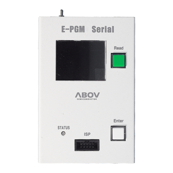
Page 11: Figure 5. E-Pgm Serial Top And Side Views For Function Description
E-PGM+ / E-GANG4/6 / E-PGM Serial User’s Manual 2. Hardware Figure 5 and the following list describe external features of the E-PGM Serial. Figure 5. E-PGM Serial Top and Side Views for Function Description ① 10-pin IDC connector for In-System Programming (ISP) ②... -
Page 12: E-Gang4/E-Gang6 Programmer
ABOV’s microcontrollers with a gang mode that allows multiple devices to be programmed simultaneously. The E-GANG4 and E-GANG6 consist of four or six E-PGM+s, respectively. In addition, it includes a power control board and USB-HUB. -
Page 13: Figure 8. E-Gang6 Top And Side Views For Function Description
E-PGM+ / E-GANG4/6 / E-PGM Serial User’s Manual 2. Hardware Figure 8 and the following list describe external features of the E-PGM+. Figure 8. E-GANG6 Top and Side Views for Function Description ① 10-pin IDC connector for In-System Programming (ISP) ②... - Page 14 2. Hardware E-PGM+ / E-GANG4/6 / E-PGM Serial User’s Manual ⑦ LED Indicator with red/green illumination shows the current status when writing is complete. — Red for FAIL — Green for PASS ⑧ A button for the simultaneous programming for all the four or six gangs ⑨...
-
Page 15: Pin Configuration
E-PGM+ / E-GANG4/6 / E-PGM Serial User’s Manual 2. Hardware Pin Configuration 2.3.1 40-pin DIP TEXTOOL Socket The E-PGM+ and E-GANG4/6 (except for E-PGM Serial) use specific sockets to program a device or a gang of devices. Users should place the appropriate socket and adapter on the 40-pin DIP TEXTOOL socket of the E-PGM+ or E-GANG4/6 before conducting programming. -
Page 16: 10-Pin Connector
2. Hardware E-PGM+ / E-GANG4/6 / E-PGM Serial User’s Manual 2.3.2 10-pin Connector A 10-pin IDC type connector is required for On-board programming with E-PGM+, E-GANG4/6 and E-PGM Serial. The target board and 10-pin connector must be connected correctly for programming. -
Page 17: Software
Software and firmware of the E-PGM+, E-GANG4/6 and E-PGM Serial can be downloaded from the ABOV Semiconductor’s website. The firmware for individual devices has been developed and fully tested by us, and the certified version of program is uploaded to our website. -
Page 18: Software Installation
E-PGM+ / E-GANG4/6 / E-PGM Serial User’s Manual Software Installation To install the software, follow the steps below: 1. At the ABOV Semiconductor’s website www.abovsemi.com, go to the “Development Tools > Programmer > E-PGM+ / E-Gang4/6 / E-PGM Serial” menu. -
Page 19: Figure 13. Windows Security
E-PGM+ / E-GANG4/6 / E-PGM Serial User’s Manual 3. Software 6. Click the ‘Install’ button if the dialog box pops up as shown in Figure 13: Figure 13. Windows security 7. After executing the ‘exe‘ file, the window shown in Figure 14 appears if the installation is successful. -
Page 20: Figure 15. Device Manager
3. Software E-PGM+ / E-GANG4/6 / E-PGM Serial User’s Manual 8. Connect the E-PGM+ or E-GANG4/6 to the PC, and turn it on. The E-PGM+ or E- GANG4/6 should be automatically recognized and displayed in Device Manager as shown in Figure 15. Figure 15. -
Page 21: Figure 17. Windows' Warning Message
E-PGM+ / E-GANG4/6 / E-PGM Serial User’s Manual 3. Software 10. If the executable cannot be executed with a pop-up shown in Figure 17, right-click on the file for the context menu. Figure 17. Windows’ Warning Message 11. . Select the Properties and click the Unblock under Security. Then, double-click the executable (E-PGM+.exe) to run the program again. -
Page 22: Software Ui Descriptions
3. Software E-PGM+ / E-GANG4/6 / E-PGM Serial User’s Manual Software UI Descriptions In this section, software functions are introduced. ⑮ ① ⑪ ⑩ ② ⓐ ⓑ ③ ④ ⑤ ⑥ ⑦ ⑫ ⑧ ⑨ ⑬ ⑭ Figure 19. E-PGM+ PC Program ①... -
Page 23: Figure 21. Select Hex File Type
E-PGM+ / E-GANG4/6 / E-PGM Serial User’s Manual 3. Software ② The ‘Load Hex’ button selects a hex file to write to the device. Before selecting a hex file, it is desirable to check the checksum of the file. Please make sure that it matches the checksum value displayed in the GUI after the file is loaded. -
Page 24: Figure 23. Displayed Progress Bar
3. Software E-PGM+ / E-GANG4/6 / E-PGM Serial User’s Manual ③ The ‘Update’ button is used to update the tool with the finalized settings. Pressing this button updates the tool with the hex file and option values. The progress bar displays the progress of the update as show in Figure 23. -
Page 25: Figure 25. Device Password
E-PGM+ / E-GANG4/6 / E-PGM Serial User’s Manual 3. Software Lock password After writing hex code write, password lock is enabled. b. The 12-byte hex-value for password is programmed. Unlock password Check device-id if password is enabled. b. Then the 12-byte hex-value for password are compared. If password is matched, password-lock is disabled. -
Page 26: Figure 26. Device Select
3. Software E-PGM+ / E-GANG4/6 / E-PGM Serial User’s Manual ⑧ The ‘Device Select’ button is the first button to press after starting programming. When this button is pressed, the list of device categories is displayed as shown in Figure 26. Click + or - to see the specific devices under each category, and select the desired device. -
Page 27: Figure 28. Choose Type
E-PGM+ / E-GANG4/6 / E-PGM Serial User’s Manual 3. Software ⑪ This button allows users to select a language. The supported languages in E-PGM+ and E-GANG4/6 are English and Chinese. Choose the desired language. ⑫ The ‘OFF LINE’ area supports saving and loading of HPO by running the software without the E- PGM+ and E-GANG4/6 connections. -
Page 28: Figure 30. Set Vdd
3. Software E-PGM+ / E-GANG4/6 / E-PGM Serial User’s Manual To get a checksum without a PC connection, Press the ‘Save HPO’ button. b. Select a tool-type. E-PGM +: E-PGM+, E-GANG4/6 E-PGM Serial: E-PGM Serial Select a device. d. -
Page 29: Figure 31. Tool Options: Erase Data Flash
E-PGM+ / E-GANG4/6 / E-PGM Serial User’s Manual 3. Software ⑭ The ‘Tool Options’ button erases Data Flash. If users select the ‘Erase Data Flash’ in Figure 31, the Data Flash is erased during write-sequence. Supported devices are A33G527 and A33G526. Figure 31. -
Page 30: Figure 33. Options Of Config. Serial Id
3. Software E-PGM+ / E-GANG4/6 / E-PGM Serial User’s Manual As shown in Figure 33, users can set the options of the ‘Config. Serial ID’. Figure 33. Options of Config. Serial ID Start addr: Start address of serial-ID b. Length: Length of serial-id, 4-byte or 8-byte Value: ID value d. -
Page 31: Figure 34. Tool Options: Config. Limit Number Of Write
E-PGM+ / E-GANG4/6 / E-PGM Serial User’s Manual 3. Software The ‘Tool Options’ button also enables the ‘Set Limit Number of Write.’ Figure 34. Tool Options: Config. Limit Number of Write Figure 35. Write Counter Enable the ‘Limit Number of Write’. b. -
Page 32: Figure 36. Log Dialog
3. Software E-PGM+ / E-GANG4/6 / E-PGM Serial User’s Manual ⑮ The Log dialog shows the progress and results in real time. Users can check the problems and solutions that occurred before progress recording. Figure 36. Log Dialog... -
Page 33: Device Selection
E-PGM+ / E-GANG4/6 / E-PGM Serial User’s Manual 3. Software Device Selection The E-PGM+ PC program is used jointly by E-Gang4 and E-Gang 6. The number of ports is displayed in the GUI when any of the products is connected: 1 port for E-PGM+ and E-PGM Serial; 4 ports for E-GANG4;... - Page 34 3. Software E-PGM+ / E-GANG4/6 / E-PGM Serial User’s Manual ① Click the ‘Device Select’ button to select a device. ② Click the ‘Load Hex’ button to select a hex file for IC programming. ③ Selecting a hex file pops up the option dialog box. Refer to the device’s manual, and select the appropriate options according to application characteristics.
-
Page 35: Programmer Self Check
E-PGM+ / E-GANG4/6 / E-PGM Serial User’s Manual 3. Software Programmer Self Check The Programmer supports a function of Self Check. For this, users need to follow the procedure below: 1. Remove a device in a tool. 2. Run the ‘E-PGM+.exe’ file. 3. -
Page 36: Figure 40. Button Of Programmers
3. Software E-PGM+ / E-GANG4/6 / E-PGM Serial User’s Manual Figure 40. Button of Programmers The Self Check results are displayed on the Programmer’s LCD screen. Figure 41 shows example results on the LCD screen. (a ) Pass (c) Fail Figure 41. -
Page 37: Programming Error Messages
E-PGM+ / E-GANG4/6 / E-PGM Serial User’s Manual 3. Software Programming Error Messages Errors may occur during programming. Causes of the errors are not displayed in detail due to the limited space of the LCD screen. Instead, a brief error message is displayed and the details of each error are given in Table 5. -
Page 38: Troubleshooting
3. Software E-PGM+ / E-GANG4/6 / E-PGM Serial User’s Manual Troubleshooting 3.7.1 Error Message: ‘The program can’t start because WDAPI1010.dll is missing.‘ Figure 42. Error Message of WDAPI1010.DLL Cause) WDAPI1010.DLL is not found in the ‘C:\Windows’ folder. Solution) If the device driver has been set up, the missing file can be copied into the ‘C:\Windows’ folder. 3.7.2 Error Message: ‘No firmware found’... -
Page 39: Error Message: 'No Valid License' Or 'Received An Invalid 32-Bit Loctl
E-PGM+ / E-GANG4/6 / E-PGM Serial User’s Manual 3. Software 3.7.3 Error Message: ‘No valid license‘ or ‘Received an invalid 32-bit LOCTL’ Figure 44. Error Message of Validity Cause) The existing ‘windrvr6.sys’ file is invalid. Solution) 1. Close the E-PGM+ S/W. 2. -
Page 40: Connection Of Handler
The hardware description for the handler connection is provided in the following sections. E-PGM+ / E-PGM Serial Handler Connections The software and firmware for the E-PGM+, E-GANG4/6, and E-PGM Serial are available for download from ABOV’s website (www.abovsemi.com). VCC: 3.3V power output from the E-PGM+ / E-PGM Serial Programmer ... -
Page 41: E-Gang4 Handler Connections
E-PGM+ / E-GANG4/6 / E-PGM Serial User’s Manual 4. Connection of Handler E-GANG4 Handler Connections The software and firmware for the E-PGM+, E-GANG4/6 and E-PGM Serial are available for download from ABOV’s website (www.abovsemi.com). Built-in internal isolator circuit ... -
Page 42: E-Gang6 Handler Connections
4. Connection of Handler E-PGM+ / E-GANG4/6 / E-PGM Serial User’s Manual E-GANG6 Handler Connections The software and firmware for the E-PGM+, E-GANG4/6 and E-PGM Serial are available for download from ABOV’s website (www.abovsemi.com). Built-in internal isolator circuit ... -
Page 43: Connecting Multiple E-Pgm+ Units
E-PGM+ / E-GANG4/6 / E-PGM Serial User’s Manual 5. Connecting Multiple E-PGM+ Units Connecting Multiple E-PGM+ Units As an alternative to the handler, users can connect multiple E-PGM+ units between Start and GND pins, respectively, as shown in Figure 49. With this configuration, the button inputs on any single Programmer are delivered to all the connected units. -
Page 44: Pcb V5.5 Sw3 Settings
6. PCB V5.5 SW3 Settings E-PGM+ / E-GANG4/6 / E-PGM Serial User’s Manual PCB V5.5 SW3 Settings MC97F1104S, MC97F1204S, and MC97F1316S require a higher VPP of 17V when programmed, and therefore users need to set the SW3 switch in the Step-up position to ensure a maximum VPP level of 19V. - Page 45 E-PGM+ / E-GANG4/6 / E-PGM Serial User’s Manual 6. PCB V5.5 SW3 Settings Figure 51. Insertion of 200 Ohms in VPP Line NOTES: If other signals affect communication in ISP mode, disconnect them from the pins (DSDA/DSCL) using a jumper or switch. A 200Ω...
-
Page 46: Revision History
Revision History E-PGM+ / E-GANG4/6 / E-PGM Serial User’s Manual Revision History Version Date Description 1.0.3 Mar. 12, 2021 First released. - Page 47 ABOV Semiconductor ("ABOV") reserves the right to make changes, corrections, enhancements, modifications, and improvements to ABOV products and/or to this document at any time without notice. ABOV does not give warranties as to the accuracy or completeness of the information included herein. Purchasers should obtain the latest relevant information of ABOV products before placing orders.
Need help?
Do you have a question about the E-PGM+ and is the answer not in the manual?
Questions and answers