Table of Contents
Advertisement
Leader of Microcontroller Technology
Leader of Microcontroller Technology
Leader of Microcontroller Technology
Global Top Smart MCU Innovation Company
Global Top Smart MCU Innovation Company
Global Top Smart MCU Innovation Company
E-PGM+
E-GANG4/E-GANG6
E-PGM Serial
User Manual
Version 1.0.0
Jun. 28, 2019
For additional information or inquiry, please contact ABOV Semiconductor
or visit its website at www.abov.co.kr.
Advertisement
Table of Contents

Related Manuals for Abov E-PGM+


Summary of Contents for Abov E-PGM+
- Page 1 Global Top Smart MCU Innovation Company Global Top Smart MCU Innovation Company Global Top Smart MCU Innovation Company E-PGM+ E-GANG4/E-GANG6 E-PGM Serial User Manual Version 1.0.0 Jun. 28, 2019 For additional information or inquiry, please contact ABOV Semiconductor or visit its website at www.abov.co.kr.
- Page 2 Revision History Date Date Version Version Description Description Jun. 28, 2019 Jun. 28, 2019 1.0.0 1.0.0 Document created. Document created. E-PGM+ E-GANG4/E-GANG6 E-PGM Serial Page 2 / 33 Version 1.0.0...
-
Page 3: Table Of Contents
Contents Chapter 1. Introduction ........Chapter 2. - Page 4 Figure 6 E-PGM serial exterior view ....... Figure 7 E-PGM Serial top and side views for function description ....Figure 8 40-pin DIP TEXTOOL socket and programming pin assignment .
-
Page 5: Chapter 1. Introduction
Introduction Chapter 1. Introduction E-PGM+, E-GANG4/6 and E-PGM Serial series are universal programming equipment for the ABOV Semiconductor’s MCU series, delivering superior performance and reliability. This products line has the following features: • Deliver high programming speed for mass manufacturing •... -
Page 6: Chapter 2. Hardware
Hardware Chapter 2. Hardware 2.1 Specifications • Product name: E-PGM+, E-GANG4/6, E-PGM Serial • Standalone type universal programmer • External 15 VDC Power supply • Dimensions (W x D x H) – E-PGM+: 8.3 cm x 14.5 cm x 3.3 cm –... -
Page 7: Functions
The functions of E-PGM+, E-GANG4/6 and E-PGM Serial are described below: 2.3.1 E‐PGM+ E-PGM+ is a standalone-type universal programmer capable of programming ABOV’s all microcontroller series. It consist of a main programmer unit and target device socket, and socket adaptor parts. -
Page 8: Figure 1 E-Pgm+ With Target Socket Module
Functions Figure 1: E-PGM+ with target socket module Exterior features of E‐PGM+ Figure 2: E-PGM+ top and side views for function description 10-pin IDC connector for in-system programming (ISP) RS-232C serial communication port (external bar code reader interface port) SWD port for firmware update and development purposes (not for use) Button for programming the target device Button for reading the target device E-PGM+ E-GANG4/E-GANG6 E-PGM Serial Page 8 / 33... -
Page 9: E-Gang4/E-Gang6
E-GANG4 and E-GANG6 are standalone-type universal gang programmers capable of programming ABOV’s all microcontroller series in gang mode, which enables programming multiple devices at once. E-GANG4 and E-GANG6 consist of a main programmer unit, target device socket, and socket adaptor parts. -
Page 10: Figure 5 E-Gang6 Exterior View For Function Description
Functions Exterior features of E‐GANG6 Figure 5: E-GANG6 exterior view for function description 10-pin IDC connector for in-system programming (ISP) SWD port for firmware update and development purposes (not for use) Button for programming the target device “G1” only Button for reading the target device LCD screen for information display—device name, checksum data, and options. -
Page 11: E-Pgm Serial
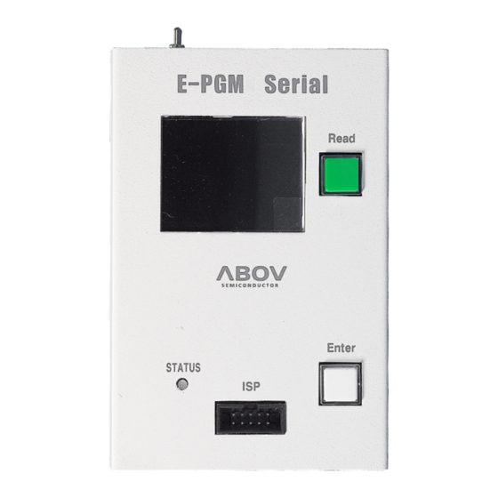
USB mini-B connector to a PC 2.3.3 E‐PGM Serial E-PGM Serial is a standalone ISP type universal programmer capable of programming ABOV’s flash microcontroller series—94/95/96/97XXXX series (excluding 97F1104S/1204S/1316S) and all 32-bit microcontrollers. It does not have a TEXTOOL socket and is designed only for on-board manufacturing purposes. -
Page 12: 40-Pin Dip Textool Socket Pin Configuration
The user should place the appropriate socket and adapter on the 40-pin DIP TEXTOOL socket before conducting programming. ABOV Semiconductor provides all sockets and adaptors compatible with E- PGM+ and E-GANG4/6. Please refer to the Socket and Adaptor Selection Guide for your target device. -
Page 13: 10-Pin Connector Pin Configuration
10-pin connector pin configuration Figure 8: 40-pin DIP TEXTOOL socket and programming pin assignment Table 2: Pin name and assignment 40-pin DIP socket 40-pin DIP socket Pin no. Pin no. ISP connector ISP connector CLOCK CLOCK DATA DATA VPP/Reset VPP/Reset RunFlag/Boot RunFlag/Boot 2.5 10‐pin connector pin configuration... -
Page 14: Figure 9 10-Pin Idc Connector Pin Assignment
10-pin connector pin configuration Figure 9: 10-pin IDC connector pin assignment Table 3: 10-pin IDC connector pin configuration for each device group Supported signals Supported signals AC33M6128/8128, AC33M6128/8128, MC80F7708 UART MC80F7708 UART Pin no. Pin no. 32-bit SWD 32-bit SWD AC33M3064/4064 AC33M3064/4064 MCU UART-RX... -
Page 15: Chapter 3. Software
Chapter 3. Software 3.1 Software releases The software and firmware of E-PGM+, E-GANG4/6 and E-PGM Serial can be downloaded from ABOV Semiconductor’s website. The firmware of individual devices is developed and fully tested by ABOV Semiconductor, and only certified versions are uploaded to the website. - Page 16 Software installation 5. Run USB_driver_install.exe. 6. Click Install if the dialog below pops up: E-PGM+ E-GANG4/E-GANG6 E-PGM Serial Page 16 / 33 Version 1.0.0...
- Page 17 Software installation 7. After running the exe file, the window below should appear if successful. The installation takes one to three minutes depending on your PC environment. • Driver installation is complete when “completed successfully” appears at the bottom of the CMD window. 8.
- Page 18 Software installation 9. Unzip the E-PGM+ Software package downloaded in Step 2. In the created folder, double-click the executable (E-PGM+.exe) to run the program. If the exe file cannot be executed with the following message popping up, Note: Right-click the file for the context menu, select Properties, and click Unblock under Security.
-
Page 19: Software Ui Descriptions
Software UI descriptions 3.3 Software UI descriptions Below are descriptions of the software functions: The Ver. Info button displays the software version. When the button is pressed, a dialog box will pop up to show the software version, date of finalization, and developer’s e-mail address. Version 1.0.0 Page 19 / 33 E-PGM+ E-GANG4/E-GANG6 E-PGM Serial... - Page 20 Software UI descriptions The Load button is used to select a hex file to write to the device. Before selecting a hex file, it is recommended to check the checksum of the file. Make sure that it matches the checksum value displayed in the GUI after the file is loaded.
- Page 21 Software UI descriptions The Option section shows the hexadecimal value of a selected option. Option values must also be checked in the programming process. The Device Select button is the first button to press after starting programming. When the button is pressed, the list of device categories is displayed.
- Page 22 Software UI descriptions The OFF LINE section is used to save and load the HPO file without connecting a programming equipment. Under the OFF LINE section the user can create a HPO file for a programming project or verifying the options and content of a HPO project in advance. Once the Save HPO button is clicked, the Load Hex button will be activated.
-
Page 23: Device Selection
Device selection The Log dialog shows the progress and results in real time. You can check the problems and solutions that occurred before progress recording. 3.4 Device selection The E-PGM+ software program is used jointly by E-GANG4, E-GANG6 and E-PGM Serial. The number of ports is automatically displayed in the dialog box when any of the programmers is connected (E-PGM+ and E-PGM Serial: 1 port, E-GANG4: 4 ports, E-GANG6: 6 ports). - Page 24 Device selection 1. Click Device to select a device. 2. Click Load to select a hex file for IC programming. 3. The dialog box for selecting the option of the hex file pops up. Refer to the device’s manual, and select the appropriate options according to application characteristics.
-
Page 25: Programming Error Messages
Programming error messages 3.5 Programming error messages Errors may occur during programming. The causes of errors cannot be presented in detail due to the limited space of the LCD screen. Instead, a brief error message appears, and the details of each error are given below. -
Page 26: Error Message: "No Firmware Found" Or "Device File Not Found
Troubleshooting Solution If you have set up the device driver, the missing file can be copied into the C:\Windows folder. 3.6.2 Error message: “No firmware found” or “Device file not found!” Cause The firmware folder and E-PGM.txt file are not located in the same folder. Solution If you want to execute this on the desktop, you need to use a desktop shortcut. - Page 27 Troubleshooting Cause The existing windrvr6.sys file is invalid. Solution 1. Disconnect the USB line. 2. Run USB_driver_unistall.exe (Version 1.7). 3. Delete C:\Windows\System32\drivers\windrvr6.sys. 4. Copy windrvr6.sys from the driver installation files to the following path: • 64bit: Copy x64\windrvr6.sys to C:\Windows\System32\drivers\ •...
-
Page 28: Chapter 4. Connection To Handler
Connection to handler Chapter 4. Connection to handler The E-PGM+, E-GANG4/6 and E-PGM Serial is designed to maximize the efficiency of device programming when connected with a handler—an automated mass-production machine. The connected handler receives the Enter button signal and communication signals (DSDA, DSCL) required for device programming from the programming equipment (E-PGM+, E-GANG4/6 and E-PGM Serial). -
Page 29: E-Gang4 Handler Connections
E-GANG4 handler connections 4.2 E‐GANG4 handler connections • Internal isolator • Handler 5V (3.3V) power used • Output > Good/fail indicator signal (active: “L”) • Input > Start key (active: “L”) Version 1.0.0 Page 29 / 33 E-PGM+ E-GANG4/E-GANG6 E-PGM Serial... -
Page 30: E-Gang6 Handler Connections
E-GANG6 handler connections 4.3 E‐GANG6 handler connections • Internal isolator • Handler 5V (3.3V) power used • Output > Good/fail indicator signal (active: “L”) • Input > Start key (active: “L”) E-PGM+ E-GANG4/E-GANG6 E-PGM Serial Page 30 / 33 Version 1.0.0... -
Page 31: Chapter 5. Connecting Multiple E-Pgm+ Units
Connecting multiple E-PGM+ units Chapter 5. Connecting multiple E‐PGM+ units As an alternative to using a handler, you can connect multiple E-PGM+ units between their Start and Gnd pins, respectively, as shown below. With this configuration, your button inputs on any single programmer are delivered to all the connected units. -
Page 32: Chapter 6. For Mc97F1104S/1204S/1316S Only
For MC97F1104S/1204S/1316S only Chapter 6. For MC97F1104S/1204S/1316S only MC97F1104S, MC97F1204S, and MC97F1316S require a higher Vpp of 17V when programmed, and so you need to set the SW3 switch in the Step-up position to ensure a maximum Vpp level of 19V. When programming any other devices, on the other hand, you must set the switch is in the Ext position to limit the maximum Vpp level to 15V. -
Page 33: Figure 12 Insertion Of A 200 Ohm Resistor In Vpp Line
For MC97F1104S/1204S/1316S only Figure 12: Insertion of a 200 ohm resistor in VPP line Note: 1. If other signals affect the communication in ISP mode, disconnect them from pins (DSDA/DSCL) using the jumper or switch. 2. A 200 Ω resistor must be installed at the target board. Without it, the MCU could be damaged because of a high voltage (17.0 V).
Need help?
Do you have a question about the E-PGM+ and is the answer not in the manual?
Questions and answers