
Subscribe to Our Youtube Channel
Related Manuals for Abov AT3212U


Summary of Contents for Abov AT3212U
- Page 1 AT3212U Demo Board Quick Start Guide STDEMO-AT3212U-KEY-A Quick Start Guide Version 1.00 Global Top Smart MCU Innovator, ABOV Semiconductor www.abovsemi.com...
-
Page 2: Table Of Contents
Contents AT3212U Demo board quick start guide Contents Introduction ............................ 4 User requirements .......................... 5 Hardware ..........................5 2.1.1 I2C to UART Board ....................5 2.1.2 Touch Demo Board ....................5 Software ..........................6 Reference documents ......................6 System requirements ......................7 ABOV website ........................ - Page 3 List of figures Figure 1. I2C to UART Board Layout (Hardware) ................... 5 Figure 2. AT3212U Touch Board Layout (Hardware) ................5 Figure 3. AT GUI Program (Software) ..................... 6 Figure 4. Window PC and Micro B Cable ....................7 Figure 5.
-
Page 4: Introduction
ABOV Logic Type Touch Key. In this document, we introduce an AT GUI program and a method to operate AT3212U Touch Demo Board with examples. By reading this document thoroughly, you can learn the easy way to develop the... -
Page 5: User Requirements
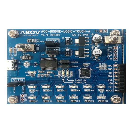
AT3212U Demo board quick start guide 2. User requirements User requirements Hardware 2.1.1 I2C to UART Board Figure 1. I2C to UART Board Layout (Hardware) 2.1.2 Touch Demo Board Figure 2. AT3212U Touch Board Layout (Hardware) -
Page 6: Software
2. User requirements AT3212U Demo board quick start guide Software You can debug using the AT GUI program. Figure 3. AT GUI Program (Software) Reference documents AT3212U Quick Guide AT3212U HW Manual AT3212U Schematic Product User’s Manual ... -
Page 7: System Requirements
AT3212U Demo board quick start guide 2. User requirements System requirements Windows PC (7, 8, 10) USB Micro B type cable Figure 4. Window PC and Micro B Cable ABOV website For detailed information about the corresponding software and documents, you can visit our website at https://www.abovsemi.com. -
Page 8: Building And Running Project
3. Building and running project AT3212U Demo board quick start guide Building and running project Running the AT GUI program makes it easier to start the Touch Demo Board. Follow the steps below to start the Demo Board: Step 1. -
Page 9: Prepare The I2C To Uart Board And Touch Demo Board
AT3212U Demo board quick start guide 3. Building and running project Prepare the I2C to UART Board and Touch Demo Board 3.1.1 Hardware components of the I2C to UART Board The I2C to UART Board operates as an I2C Master based on the Touch Demo Board, and contacts your PC through UART communication. -
Page 10: Hardware Components Of The Shield Board
3. Building and running project AT3212U Demo board quick start guide 3.1.2 Hardware components of the Shield Board AT3212 (24-QFN) chip: Touch Sensing 12CH (channel) and LED 4 pins are supported. The 2mm (2T) Thick plastic cover is attached to the Touch PAD. -
Page 11: Set Up The I2C To Uart Board And Touch Demo Board
AT3212U Demo board quick start guide 3. Building and running project Set up the I2C to UART Board and Touch Demo Board 3.2.1 Set jumpers to control the I2C to UART Board You can select a power source between USB power and external power using a jumper pin (recommended to use +5V USB power). -
Page 12: Connect To The I2C To Uart Board To Use The Touch Demo Board
3. Building and running project AT3212U Demo board quick start guide 3.2.2 Connect to the I2C to UART Board to use the Touch Demo Board Connect a header socket of the Touch Demo Board and the header pin of the I2C to UART Board as shown in Figure 9. -
Page 13: Connect The I2C To Uart Board To Your Pc
AT3212U Demo board quick start guide 3. Building and running project Connect the I2C to UART Board to your PC 3.3.1 Connect PC via USB on the I2C to UART Board Connect the USB 2.0 (micro-B type) cable to the I2C to UART Board as shown in Figure 10. -
Page 14: At Gui Program Practice
3. Building and running project AT3212U Demo board quick start guide AT GUI program practice 3.4.1 Run the AT GUI program Run the AT GUI program by double clicking over the icon shown in Figure 11. Figure 11. AT GUI Program Icon After the program starts, the COM port number is displayed on the screen as shown in Figure Click on the ‘RUN’... -
Page 15: Viewing Values In At Gui Program
AT3212U Demo board quick start guide 3. Building and running project 3.4.2 Viewing values in AT GUI program When a Touch Key on the Demo Board is touched by your finger, a corresponding LED on the Communication Board (I2C to UART Board) lights up. At the same time, the GUI program displays the corresponding key in red, as shown in Figure 13. -
Page 16: Options Of Auto Read Selection
3. Building and running project AT3212U Demo board quick start guide 3.4.3 Options of Auto Read Selection Key: It supports key display activation. Figure 14. Run (Start Code Execution) -
Page 17: Figure 15. Data Menu Options
AT3212U Demo board quick start guide 3. Building and running project Data: RAW, Baseline, Threshold, Percentage RAW Data (Original touch sensitivity value) Baseline Data (Baseline reference value) C. Threshold (THD; Touch detection reference value) D. Percentage (Current Sensitivity percentage based on the THD value of 100%) Example) The percentage value of 223% implies that the Current Sensitivity value is 2.23 times... -
Page 18: View Graph (Plot)
3. Building and running project AT3212U Demo board quick start guide 3.4.4 View Graph (Plot) Press the ‘Graph’ button at the top of the GUI program or press ‘F1’ function key. You can see the values of all channels on the screen, as shown in Figure 16. -
Page 19: Register Value Settings
AT3212U Demo board quick start guide 3. Building and running project 3.4.5 Register value settings For the register value settings, we provide two methods: Part 1 and Part 2. Using the Part 1, you can mark check boxes or write values to set the registers. Using the Part 2, you can write I2C commands directly to set the registers. -
Page 20: Figure 18. Register Value Settings (Part2)
3. Building and running project AT3212U Demo board quick start guide Part 2: Write register address and setting value in the Part 2-input window, as shown in Figure 18. Then, press the ‘Write’ button. Or you can enter Multi-byte data that has the address as a starting address. Then, press the ‘Write’... -
Page 21: Software Description
AT3212U Demo board quick start guide 3. Building and running project Software description 3.5.1 Flow chart for overall workflow At the initial stage when the external power is applied, the register setting values required for the I2C Communication are entered once. -
Page 22: Touch Mode Selection
3. Building and running project AT3212U Demo board quick start guide 3.5.2 Touch Mode Selection Touch Mode operates in two sub-modes: Fast Mode (Active Mode) and Sleep Mode (Snap Mode). In Fast Mode, Touch Sensor always proceeds with its operation (including Touch Sensing operation). -
Page 23: How To Enter Sleep Mode
AT3212U Demo board quick start guide 3. Building and running project 3.5.3 How to enter Sleep Mode When entering Sleep Mode from Fast Mode (Active Mode), make sure to disable Fast Mode first and then, enable Sleep Mode. Fast Mode Disable: CTRL1 &= (~0x80);... -
Page 24: I2C Communication Method During Sleep Mode
3. Building and running project AT3212U Demo board quick start guide 3.5.4 I2C Communication method during Sleep Mode If a Touch Event (Touch ON or OFF) is generated in Sleep Mode, the INT output pin releases Low Pulses. At this point, Active Mode is maintained for the time set in the STOP_DELAY register. -
Page 25: Register Value Settings And Digital Output Pin Use
AT3212U Demo board quick start guide 3. Building and running project 3.5.5 Register value settings and digital output pin use Initial setups of the Touch detection reference value (THD; Threshold), Touch Sensing CH (channel), and other registers are possible. -
Page 26: Loop Operation And Register Value Update
3. Building and running project AT3212U Demo board quick start guide 3.5.6 Loop operation and register value update During Loop operation, Touch Sensing and the result values are stored. At this point, a certain value in a register can be modified through I2C Communication. -
Page 27: I2C Master Example Code
AT3212U Demo board quick start guide 3. Building and running project 3.5.7 I2C master example code AT3212.h Figure 26. AT3212.h... - Page 28 3. Building and running project AT3212U Demo board quick start guide Figure 26. AT3212.h (continued)
-
Page 29: Figure 27. At3212.C
AT3212U Demo board quick start guide 3. Building and running project AT3212.c Figure 27. AT3212.c... - Page 30 3. Building and running project AT3212U Demo board quick start guide Figure 27. AT3212.c (continued)
-
Page 31: Revision History
AT3212U Demo board quick start guide Revision history Revision history Version Date Description 1.00 21.02.19 Document created... - Page 32 ABOV Semiconductor ("ABOV") reserves the right to make changes, corrections, enhancements, modifications, and improvements to ABOV products and/or to this document at any time without notice. ABOV does not give warranties as to the accuracy or completeness of the information included herein. Purchasers should obtain the latest relevant information of ABOV products before placing orders.
Need help?
Do you have a question about the AT3212U and is the answer not in the manual?
Questions and answers