Advertisement
Table of Contents
- 1 Table of Contents
- 2 Receiving
- 3 Installation
- 4 Refrigerator and Freezer Operation
- 5 Digital Temp Display ("-Dtd" Model)
- 6 Control Center - Temperature Monitor System ("-Da" Model)
- 7 Chart Recorder Operation ("-Cr" Model)
- 8 Quick Troubleshooting Guide
- 9 Maintenance and Cleaning
- 10 Horizon Scientific, Inc. Product Warranty
- Download this manual
Part number 20057, Rev 0
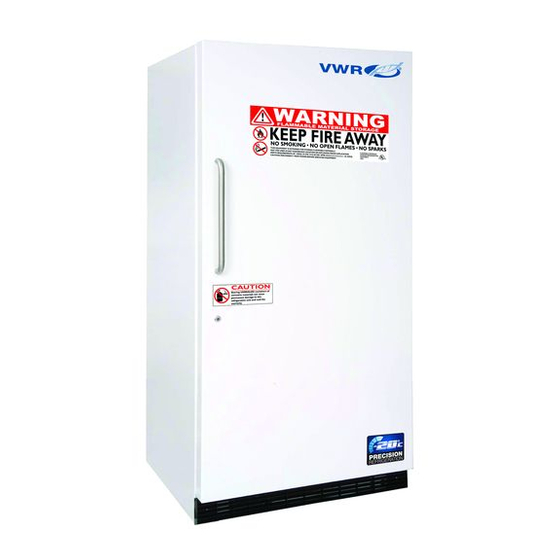
FLAMMABLE STORAGE REFRIGERATORS, FREEZERS, & DUAL-TEMP UNITS
MODELS FSR-1404, FSR-1704, FSR-2004, FSR-3004,
FSF-1420, FSF-1720, FSF-2020, FSF-3020, FS-RFC-30
(with options, "-DTD" Digital Temp Display, "-DA" CONTROL CENTER
Temp Alarm and/or "-CR" Chart Recorder)
This manual describes how to operate and care for your appliance to get the best, most efficient, performance.
Note to Customer:
This merchandise was carefully packed and thoroughly inspected before leaving our plant. Responsibility for its
safe delivery was assumed by the carrier upon acceptance of the shipment. As directed on the side of your
packing carton, claims for loss or damage sustained in transit must be made on the carrier as follows:
A.) Visible Loss, Damage, Shortage External Evidence of Loss or Damage: This type of damage must be noted on
the freight bill and acknowledged by the carrier's agent (driver) at time of delivery. Make sure you get a signed
copy. Send a written request for an inspection to the carrier.
B.) Concealed Damage: This type of damage may not be discovered until the unit is being unpacked. When
concealed damage is discovered, stop unpacking immediately and contact the carrier immediately to report
the claim and request an inspection. This should be done as soon as possible and, in any case, must be done
within 15 days or receiving the merchandise. If at all possible, do not move the item and save all packaging
material for carrier's inspection.
C.) FAILURE TO FOLLOW THESE INSTRUCTIONS MAY RESULT IN THE CARRIER REFUSING TO HONOR YOUR
COMPANY'S CLAIM. UNDER NO CIRCUMSTANCES SHOULD THE MERCHANDISE BE RETURNED TO THE
MANUFACTURER. NO RETURNS WILL BE ACCEPTED WITHOUT PRIOR AUTHORIZATION.
Horizon Scientific
125 Varnfield Drive
Summerville, SC 29483
Phone: 800-648-4041
Fax:
843-821-8051
OWNER'S INSTRUCTIONS
READ THIS BOOK!
Warranty:
Two-Year Parts and Labor
5 Years Compressor Parts
1
Revision Date
07/30/2013
Advertisement
Table of Contents

Related Manuals for VWR FSR-1404


Summary of Contents for VWR FSR-1404
- Page 1 Part number 20057, Rev 0 FLAMMABLE STORAGE REFRIGERATORS, FREEZERS, & DUAL-TEMP UNITS MODELS FSR-1404, FSR-1704, FSR-2004, FSR-3004, FSF-1420, FSF-1720, FSF-2020, FSF-3020, FS-RFC-30 (with options, “-DTD” Digital Temp Display, “-DA” CONTROL CENTER Temp Alarm and/or “-CR” Chart Recorder) OWNER’S INSTRUCTIONS This manual describes how to operate and care for your appliance to get the best, most efficient, performance.
-
Page 2: Table Of Contents
Part number 20057, Rev 0 TABLE OF CONTENTS RECEIVING ......................4 INSTALLATION ......................5 REFRIGERATOR AND FREEZER OPERATION ............7 DIGITAL TEMP DISPLAY (“-DTD” MODEL) ............... 8 CONTROL CENTER - TEMPERATURE MONITOR SYSTEM (“-DA” MODEL) ....9 CHART RECORDER OPERATION (“-CR” MODEL) ........... 15 QUICK TROUBLESHOOTING GUIDE .............. - Page 3 Part number 20057, Rev 0...
-
Page 4: Receiving
Part number 20057, Rev 0 RECEIVING Your unit was built, packaged, and inspected with extreme care. We shipped it to you using carriers we trust with a proven track record of careful handling, good customer service, and on time delivery. Unfortunately, regardless of all of these efforts sometimes accidents happen and occasionally those accidents result in shipping damage. -
Page 5: Installation
Part number 20057, Rev 0 INSTALLATION UNCRATING – Move your refrigerator as close to the final location as possible before unpacking. Remove the wooden planks or skid. The location should be as close as possible to the power outlet, so the extension cord is not needed. This unit requires a minimum of 4 inches of air flow space in back and 3 inches on the sides and top. - Page 6 Part number 20057, Rev 0 DOOR BINS (not applicable to all models) Your unit may come equipped with storage bins in the door. Because of the temperature characteristics of these units, items stored in these bins may not be maintained in the desired temperature band.
-
Page 7: Refrigerator And Freezer Operation
Part number 20057, Rev 0 REFRIGERATOR AND FREEZER OPERATION After the unit is properly installed and power is applied, it will take some time before the system is cooled down to temperature and cycling normally. You should wait 8 hours on the first startup before beginning to add product to the unit. -
Page 8: Digital Temp Display ("-Dtd" Model)
Part number 20057, Rev 0 DIGITAL TEMP DISPLAY (“-DTD” MODEL) The digital temp display provides a clear and digital temp readout. The probe is placed within the glycol to simulate the product temp inside the chamber. Displaying °F or °C: Remove the plastic panel located below the solar panels by using a blunt tipped tool. -
Page 9: Control Center - Temperature Monitor System ("-Da" Model)
Part number 20057, Rev 0 CONTROL CENTER - TEMPERATURE MONITOR SYSTEM (“-DA” MODEL) The temperature control center (monitor) system on the front of the unit provides the following functions- to provide an indication of the sample temperature inside of the compartment to provide a local alarm at the unit in the event an out of range temperature exists to provide the ability to connect remote systems to provide remote alarms or notifications in the event of an out of range temperature. - Page 10 Part number 20057, Rev 0 The STATUS tricolor LED shows the status of the unit. Green = normal run mode Amber = program mode Red = temperature is out of range (The light blinks off briefly each second to show the unit is active) The ALARM/TEST push-button interrupts line power, to allow testing of the battery and the alarm relay.
- Page 11 Part number 20057, Rev 0 In Programming mode, pressing the button decreases the displayed parameter value. ASIC PERATION The Control Center Monitor has two modes: NORMAL RUN MODE and PROGRAMMING MODE. In Normal Run mode, the display shows the temperature that the probe is reading to the lowest whole number, i.e., if it shows a value of 10.0ᵒ, the actual temperature can range from 10.0 to 10.9.
- Page 12 Part number 20057, Rev 0 Testing the battery: The battery recharges when the unit is plugged into line power. To test the battery, push the ALARM/TEST button on the front panel. The following should happen: The ALARM LED will flash red. ...
- Page 13 Part number 20057, Rev 0 rd (Relay Delay) If there is an alarm condition, the relay contacts will switch. The relay delay parameter allows the user to set the amount of time delay from the start of the alarm condition to the time the relay contact switches.
- Page 14 Part number 20057, Rev 0 Remote Alarm Contacts The Remote Alarm Relay is a single-pole double-throw (SPDT) relay that changes state (switches) with the loss of line power or with the presence of an alarm condition. NOTE: The relay is rated for pilot duty operation only. Do NOT use it for control switching. The relay contacts and connections are rated at 30v/1A.
-
Page 15: Chart Recorder Operation ("-Cr" Model)
Part number 20057, Rev 0 CHART RECORDER OPERATION (“-CR” MODEL) CHANGING THE CHART PAPER Press and hold the "change chart" button (#3) for approximately one (1) second until the pen begins to move to the left of the chart and then release the button. Wait until the pen has moved completely off of the chart. - Page 16 Part number 20057, Rev 0 PEN ARM CALIBRATION To check and/or adjust the recording pen(s) calibration to the outer most temperature graduation of the chart, press and hold the "change chart" button (#3) until the pen begins to move off of the chart. Once the pen(s) has moved off of the chart, again press and hold the "change chart"...
- Page 17 Part number 20057, Rev 0 temperature of the solution. The arrow buttons must be held for approximately five (5) seconds before the pen will begin to move. 3a. For two (2) pen recorders, you must first select the pen that you wish to calibrate. This is done by pressing the left (#1) arrow button to select the red pen or the right (#2) arrow button to select the blue pen.
-
Page 18: Quick Troubleshooting Guide
Part number 20057, Rev 0 QUICK TROUBLESHOOTING GUIDE Check these items before calling for service PROBLEM: POSSIBLE CAUSE / SOULTIONS: Electrical circuit is not 110-120V 60Hz. The power cord is not plugged in. No power at electrical outlet. Check to make sure Unit does not run breaker is not tripped or fuse is not blown. - Page 19 Part number 20057, Rev 0 PROBLEM: POSSIBLE CAUSE / SOULTIONS: Compressor may be overheated. Please check the room Compressor noises temp and ensure the range is within 65°F to 85°F. If the problem still exists, call for service. Door gasket is not sealing properly. Check for debris, cracks, and items passing through door at the gasket.
-
Page 20: Maintenance And Cleaning
Part number 20057, Rev 0 MAINTENANCE AND CLEANING Freezers should be defrosted whenever ¼ to ½ inch of frost has accumulated. Use the procedures in the defrosting section starting at the bottom of this page for best results. Refrigerators require little maintenance but should be cleaned periodically to keep them running efficiently. - Page 21 Part number 20057, Rev 0 On upright units with a defrost drain – remove the drain plug on the inside floor of the freezer by pulling straight out. To access the external drain tube on models with a base panel, first remove the two screws from the base panel.
-
Page 22: Horizon Scientific, Inc. Product Warranty
Part number 20057, Rev 0 HORIZON SCIENTIFIC, INC. PRODUCT WARRANTY Horizon Scientific, Inc. warrants to the original purchaser every new Horizon Scientific, Inc. refrigerated unit, the cabinet and all parts thereof, to be free from defects in material or workmanship, when such unit is installed, used, and maintained in accordance with provided instructions, for a period of two (2) years. - Page 23 Part number 20057, Rev 0 WARRANTY IS NOT TRANSFERABLE. This warranty is not assignable and applies only in favor of the original purchaser/user to whom delivered. Any such assignment or transfer shall void the warranties herein made and shall void all warranties, express or implied, including any warranty of merchantability or fitness for a particular purpose.
Need help?
Do you have a question about the FSR-1404 and is the answer not in the manual?
Questions and answers