Advertisement
Quick Links
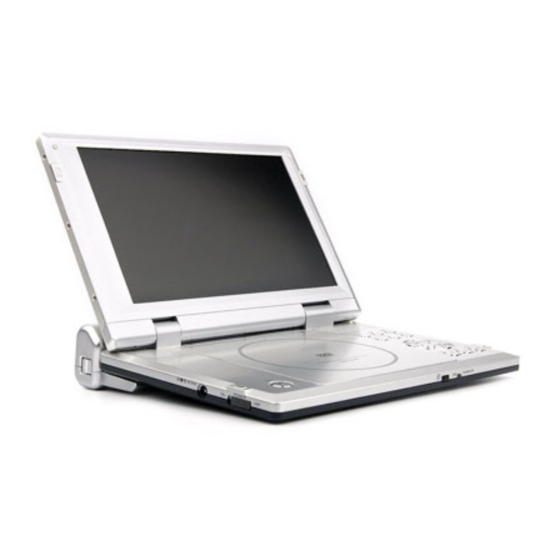
SERVI C E MANUAL
CAUTION : Before servicing this chassis, read the "PRODUCT SAFETY SERVICE FOR VIDEO PRODUCTS" section
on page 2 of this manual.
DVD and CD
PLAYER
CONTENTS
SERVICE PRECAUTIONS......................................................2,3
BLOCK DIAGRAMS...................................................................4
TROUBLE SHOOTING...........................................................5,8
BOARD DIAGRAM...............................................................9,10
REPLACEMENT PARTS LIST............................................11,23
MODEL
SDP1910
Advertisement

Related Manuals for Shinco SDP1910


Summary of Contents for Shinco SDP1910
- Page 1 SERVI C E MANUAL MODEL SDP1910 CAUTION : Before servicing this chassis, read the "PRODUCT SAFETY SERVICE FOR VIDEO PRODUCTS" section on page 2 of this manual. CONTENTS DVD and CD SERVICE PRECAUTIONS............2,3 BLOCK DIAGRAMS..............4 TROUBLE SHOOTING............5,8 PLAYER BOARD DIAGRAM...............9,10...
-
Page 2: Laser Beam Caution Label
LASER BEAM CAUTION LABEL When the power supply is being turned on, you may not remove this laser cautions label. If it removes, radiation of laser may be received. PREPARATION OF SERVICING Pickup Head consists of a laser diode that is very susceptible to external static electrocity. Although it operates properly after replacement, if it was subject to electrostatic discharge during replacement, its life might be shortened. -
Page 3: Safty Precautions
SAFTY NOTICE SAFTY PRECAUTIONS LEAKAGE CURRENT CHECK Plug the AC line cord directly into a 120V AC outlet (do Measure the AC voltage across the 1500 resistor. not use an isolation transformer for this check). Use an The test must be conducted with the AC switch on and AC voltmeter, having 5000 per volt or more sensitivity. - Page 4 OVERALL BLOCK DIAGRAM OSCILLATOR DC 9V 8M FlashROM 64M SDRAM OZ960 TC4W53 74HCU04 27MHz MX29LV008TTC-70 NT56V6620C0T-75S 27MHz UPD5100 HIGH VOLTAGE ASS'Y TFT MONITOR RF AMP & SERVO & DVD PROCESSOR DV22 MPEG-2 DECODER & VIDEO ENCODER PU mechanism D3800 R/G/B TVP5146PFP MX284 BA7660FS...
-
Page 5: Troubleshooting
1. Troubleshooting 1. No power when turned on. 2. The initial screen is not displayed on the LCD. 3. The DVD drive does not work. 4. The operation of the DVD player stops at initializing display. 5. Image output stops during the operation. 6. - Page 6 1.2 The initial screen is not displayed on the LCD. If the initial screen is not displayed on the LCD, check the following items. (1) Check the LED on the front If the LED does not light, proceed to 1.1. (2) Check the backlight If the backlight does not light up, separate.
- Page 7 1.3 The DVD drive does not work. When the DVD drive does not work after the power is turned on, check the following items and repair or replace the defective parts. (1) Press the DISC cover switch at the center of the DVD player and turn on the power.
- Page 8 1.5 Image output stops during the operation. If the image output form the media in the DVD player stops during the operation, replace the DVD drive. 1.6 No sound or abnormal sound comes out from the speakers in the DVD player. If no sound comes out form the speakers in the DVD player, check the following: (1) Check for moving images on the LCD screen Check whether or not the move of image stops in halfway.
- Page 9 SDP1910 MAIN BOARD DIAGRAM...
- Page 10 SDP1910TFT-284 TFT BOARD DIAGRAM...
-
Page 11: Electrical Parts List
ELECTRICAL PARTS LIST PART No. PART NAME Q'TY SDP1910 11079o RB-LI25LITHIUM BATTERY 21412 DVD1910 HV PCB ASS'Y 21411 DVD1910 FUNCTION PCB ASS'Y 21410 DVD1910 MAIN PCB ASS'Y 21408 DVD1910TFT-284 TFT PCB ASS'Y S8072 DV22 LOADING ASS'Y S0578e ADPV18A AC POWER ADAPTER... - Page 12 REF No. PART No. PART NAME REF No. PART No. PART NAME DVD1910 MAIN PCB ASS'Y P11013 Resistor chip 10K ¡ RESISTOR P11013 Resistor chip 10K ¡ P11013 Resistor chip 10K P11013 Resistor chip 10K ¡ ¡ P11004 Resistor chip 33 P11013 Resistor chip 10K ¡...
- Page 13 REF No. PART No. PART NAME REF No. PART No. PART NAME P11022 Resistor chip 470K R034 P11041 Resistor chip 82K ¡ ¡ P11118 Resistor chip 75K R035 P11039 Resistor chip 56K ¡ ¡ P11022 Resistor chip 470K R036 P11039 Resistor chip 56K ¡...
- Page 14 REF No. PART No. PART NAME REF No. PART No. PART NAME R511 P11002 Resistor chip 4.7 R586 P11017 Resistor chip 33K ¡ ¡ R512 P11002 Resistor chip 4.7 R587 P11009 Resistor chip 1K ¡ ¡ R513 P11032 Resistor chip 5.1K R593 P11002 Resistor chip 4.7 ¡...
- Page 15 REF No. PART No. PART NAME REF No. PART No. PART NAME P31100 Ceramic CAP 10uF/16V P31100 Ceramic CAP 10uF/16V P31100 Ceramic CAP 10uF/16V P31100 Ceramic CAP 10uF/16V P31100 Ceramic CAP 10uF/16V P20051 Capacitor chip 5.1pF P31094 EEVMC0J101P P20002 Capacitor chip 22pF P30014 Electrolytic CAP 100uF/16V P20009 Capacitor chip 1000pF P31100 Ceramic CAP 10uF/16V...
- Page 16 REF No. PART No. PART NAME REF No. PART No. PART NAME C016 P20015 Capacitor chip 0.1uF C117 P20006 Capacitor chip 100pF C018 P20009 Capacitor chip 1000pF C118 P31100 Ceramic CAP 10uF/16V C019 P20015 Capacitor chip 0.1uF C119 P31100 Ceramic CAP 10uF/16V C021 P30014 Electrolytic CAP 100uF/16V C121...
- Page 17 REF No. PART No. PART NAME REF No. PART No. PART NAME C510 P31095 EEVMC0J470R P20015 Capacitor chip 0.1uF C512 P31093 EEVMC1C100R P20015 Capacitor chip 0.1uF C513 P31093 EEVMC1C100R P20015 Capacitor chip 0.1uF C514 P31096 EEVMC0G470R P20015 Capacitor chip 0.1uF C515 P31096 EEVMC0G470R CB04...
- Page 18 REF No. PART No. PART NAME REF No. PART No. PART NAME CB78 P20015 Capacitor chip 0.1uF CB133 P20015 Capacitor chip 0.1uF CB79 P20015 Capacitor chip 0.1uF CB134 P20015 Capacitor chip 0.1uF CB81 P20015 Capacitor chip 0.1uF CB135 P20015 Capacitor chip 0.1uF CB83 P20015 Capacitor chip 0.1uF CB136...
- Page 19 REF No. PART No. PART NAME REF No. PART No. PART NAME P6659 Impedance at 100MHz:600 P1200 1SS355TE Switch Diode ¡ P6659 P5722a B240A Impedance at 100MHz:600 ¡ P6659 P1219 1N5402T Impedance at 100MHz:600 ¡ P6659 P5766 STZ6.2NT146 Impedance at 100MHz:600 ¡...
- Page 20 REF No. PART No. PART NAME REF No. PART No. PART NAME VD522 P1200 1SS355TE Switch Diode N406 a6733 HS0038B VD523 P1200 1SS355TE Switch Diode N501 P4530 NJM4558 VD524 P5067 KTA1298 N502 P4513 NJM4580 VD525 P1200 1SS355TE Switch Diode N503 P4535 CD2822CB VD535...
- Page 21 REF No. PART No. PART NAME REF No. PART No. PART NAME P11013 Resistor chip 10K P11003 Resistor chip 10 ¡ ¡ P11013 Resistor chip 10K P11003 Resistor chip 10 ¡ ¡ P11013 Resistor chip 10K P11155 Resistor chip 270K ¡...
- Page 22 REF No. PART No. PART NAME REF No. PART No. PART NAME CB17 P20015 Capacitor chip 0.1uF P31100 Ceramic CAP 10uF/16V CB18 P20015 Capacitor chip 0.1uF INDUCTOR CB19 P20015 Capacitor chip 0.1uF P6659 Impedance at 100MHz:600 ¡ CB20 P20015 Capacitor chip 0.1uF P6659 Impedance at 100MHz:600 ¡...
- Page 23 REF No. PART No. PART NAME P11013 Resistor chip 10K ¡ P11026 Resistor chip 1.2K ¡ P11013 Resistor chip 10K ¡ P11004 Resistor chip 33 ¡ P11004 Resistor chip 33 ¡ P11159 Resistor chip 820K ¡ P11226 Resistor chip 5.1K ¡...
Need help?
Do you have a question about the SDP1910 and is the answer not in the manual?
Questions and answers