Table of Contents
Advertisement
Quick Links
SERVI C E MANUAL
CAUTION : Before servicing this chassis, read the "PRODUCT SAFETY SERVICE FOR VIDEO PRODUCTS" section
on page 2 of this manual.
DVD and CD
PLAYER
CONTENTS
SERVICE PRECAUTIONS......................................................2,3
BLOCK DIAGRAMS...................................................................4
TROUBLE SHOOTING...........................................................5,8
BOARD DIAGRAM...............................................................9,10
REPLACEMENT PARTS LIST............................................11,20
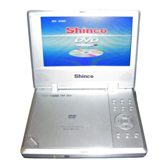
MODEL
SDP1731A
Advertisement
Table of Contents

Subscribe to Our Youtube Channel
Related Manuals for Shinco SDP1731A


Summary of Contents for Shinco SDP1731A
- Page 1 SERVI C E MANUAL MODEL SDP1731A CAUTION : Before servicing this chassis, read the "PRODUCT SAFETY SERVICE FOR VIDEO PRODUCTS" section on page 2 of this manual. CONTENTS DVD and CD SERVICE PRECAUTIONS............2,3 BLOCK DIAGRAMS..............4 TROUBLE SHOOTING............5,8 PLAYER BOARD DIAGRAM...............9,10...
-
Page 2: Laser Beam Caution Label
LASER BEAM CAUTION LABEL When the power supply is being turned on, you may not remove this laser cautions label. If it removes, radiation of laser may be received. PREPARATION OF SERVICING Pickup Head consists of a laser diode that is very susceptible to external static electrocity. Although it operates properly after replacement, if it was subject to electrostatic discharge during replacement, its life might be shortened. -
Page 3: Safty Precautions
SAFTY NOTICE SAFTY PRECAUTIONS LEAKAGE CURRENT CHECK Plug the AC line cord directly into a 120V AC outlet (do Measure the AC voltage across the 1500 resistor. not use an isolation transformer for this check). Use an The test must be conducted with the AC switch on and AC voltmeter, having 5000 per volt or more sensitivity. - Page 4 OVERALL BLOCK DIAGRAM 27MHz UPD5100 HIGH VOLTAGE ASS'Y TFT MONITOR 8M FlashROM 64M SDRAM TC4W53 74HCU04 TFT POWER MX29LV008TTC-70 DC 9V NT56V6620C0T-75S +5V -14.5V +16V 27MHz VIDEO OUT SERVO & DVD PROCESSOR KHM-252 MPEG-2 DECODER RF AMP PU mechanism D2891 &...
-
Page 5: Troubleshooting
1. Troubleshooting 1. No power when turned on. 2. The initial screen is not displayed on the LCD. 3. The DVD drive does not work. 4. The operation of the DVD player stops at initializing display. 5. Image output stops during the operation. 6. - Page 6 1.2 The initial screen is not displayed on the LCD. If the initial screen is not displayed on the LCD, check the following items. (1) Check the LED on the front If the LED does not light, proceed to 1.1. (2) Check the backlight If the backlight does not light up, separate.
- Page 7 1.3 The DVD drive does not work. When the DVD drive does not work after the power is turned on, check the following items and repair or replace the defective parts. (1) Press the DISC cover switch at the center of the DVD player and turn on the power.
- Page 8 1.5 Image output stops during the operation. If the image output form the media in the DVD player stops during the operation, replace the DVD drive. 1.6 No sound or abnormal sound comes out from the speakers in the DVD player. If no sound comes out form the speakers in the DVD player, check the following: (1) Check for moving images on the LCD screen Check whether or not the move of image stops in halfway.
- Page 9 DVD1731BM-AS MAIN PCB BOARD DIAGRAM...
- Page 10 DVD1731T-AS IF PCB BOARD DIAGRAM DVD1731H-L HV PCB BOARD DIAGRAM...
-
Page 11: Electrical Parts List
ELECTRICAL PARTS LIST PART No. PART NAME Q'TY SDP1731A 11079j RB-LI24 LITHIUM BATTERY 21328 DVD1731H-L HV PCB ASS'Y 21186 DVD1731 FUNCTION PCB ASS'Y 21385 DVD1731BM-AS MAIN PCB ASS'Y 21344 DVD1731T-AS IF PCB ASS'Y S8064 KHM-252 LOADING ASS'Y S0578e ADPV18A AC POWER ADAPTER... - Page 12 REF No. PART No. PART NAME REF No. PART No. PART NAME DVD1731BM-AS MAIN PCB ASS'Y P11000 Resistor chip 0 ¡ RESISTOR P11000 Resistor chip 0 ¡ P11038 Resistor chip 39K P11000 Resistor chip 0 ¡ ¡ P11013 Resistor chip 10K P11012 Resistor chip 4.7K ¡...
- Page 13 REF No. PART No. PART NAME REF No. PART No. PART NAME R152 P11044 Resistor chip 220K R455 P11019 Resistor chip 100K ¡ ¡ R153 P11034 Resistor chip 18K R456 P11009 Resistor chip 1K ¡ ¡ R157 P11018 Resistor chip 47K R457 P11023 Resistor chip 1M ¡...
- Page 14 REF No. PART No. PART NAME REF No. PART No. PART NAME R521 P11031 Resistor chip 3.9K P1006 Row of resistor 100 ¡ ¡ R522 P11019 Resistor chip 100K RN419 P11206 Row of resistor 22 ¡ ¡ CAPACITOR R523 P11013 Resistor chip 10K ¡...
- Page 15 REF No. PART No. PART NAME REF No. PART No. PART NAME C103 P31100 Ceramic CAP 10uF/16V C182 P30014 Electrolytic CAP 100uF/16V C104 P20009 Capacitor chip 1000pF C188 P30014 Electrolytic CAP 100uF/16V C105 P20009 Capacitor chip 1000pF C190 P30014 Electrolytic CAP 100uF/16V C110 P30014 Electrolytic CAP 100uF/16V C401...
- Page 16 REF No. PART No. PART NAME REF No. PART No. PART NAME C467 P31100 Ceramic CAP 10uF/16V C535 P30002 Electrolytic CAP 47uF/6V C471 P20051 Capacitor chip 5.1pF C536 P30014 Electrolytic CAP 100uF/16V C472 P20009 Capacitor chip 1000pF C537 P20015 Capacitor chip 0.1uF C473 P20051 Capacitor chip 5.1pF C538...
- Page 17 REF No. PART No. PART NAME REF No. PART No. PART NAME CB14 P20015 Capacitor chip 0.1uF CB55 P20015 Capacitor chip 0.1uF CB15 P20015 Capacitor chip 0.1uF CB56 P20015 Capacitor chip 0.1uF CB16 P20015 Capacitor chip 0.1uF CB57 P20015 Capacitor chip 0.1uF CB17 P20015 Capacitor chip 0.1uF CB58...
- Page 18 REF No. PART No. PART NAME REF No. PART No. PART NAME L133 P6679 10uH VD001 P5722a B240A L137 P6681 100uH VD002 P5722a B240A L140 P60003 33uH VD004 P5752 2SJ401 L403 P6817 VD101 P1219 1N5402T Impedance at 100MHz:60 ¡ L404 P6659 VD102 P90211 RN1224N332F...
- Page 19 REF No. PART No. PART NAME REF No. PART No. PART NAME VD522 P1200 1SS355TE Switch Diode N406 a6733 HS0038B VD523 P1200 1SS355TE Switch Diode N409 P4516 74HCU04 VD524 P5067 KTA1298 N412 P90157c SST39VF-080-70 4C-EI VD525 P1200 1SS355TE Switch Diode N413 P4620a BR24C02F-WE2 VD526...
- Page 20 REF No. PART No. PART NAME REF No. PART No. PART NAME CAPACITOR P11013 Resistor chip 10K ¡ CAPACITOR P31091 EEVMC1C470P P20035 Capacitor chip 1uF P31100 Ceramic CAP 10uF/16V P20012 Capacitor chip 0.01uF P31100 Ceramic CAP 10uF/16V P20015 Capacitor chip 0.1uF P31100 Ceramic CAP 10uF/16V P20035 Capacitor chip 1uF P31100 Ceramic CAP 10uF/16V...
Need help?
Do you have a question about the SDP1731A and is the answer not in the manual?
Questions and answers