
Subscribe to Our Youtube Channel
Related Manuals for HAMPTON BAY 705 114


Summary of Contents for HAMPTON BAY 705 114
- Page 1 705 114 Cohutta in Ceiling Fan Owner’s Manual Cohutta Ventilador de Techo de 1,32 Manual del Propietario...
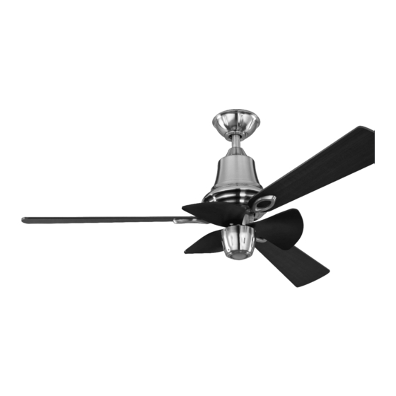
- Page 2 Hampton Bay Cohutta ®...
-
Page 3: Table Of Contents
Thank you for purchasing our ceiling fan. This product has been Cohutta manufactured with the highest standards of safety and quality. Ceiling Fan by Hampton Bay Date Purchased Table of Contents Store Purchased Safety Rules ....1 CF652KR-CHT Unpacking Your Fan . -
Page 4: Safety Rules
Safety Rules - Read and Save These Instructions After making electrical connections, spliced conductors should be To reduce the risk of electric shock, insure electricity has been turned upward and pushed carefully up into outlet box. The wires turned off at the circuit breaker or fuse box before beginning. should be spread apart with the grounded conductor and the equipment-grounding conductor on one side of the outlet box and All wiring must be in accordance with the National Electrical... -
Page 5: Unpacking Your Fan
Unpacking Your Fan Unpack your fan and check the contents. You should have the following items: Compartment cover (1) 1. Fan blades (3) 15. Loose parts bag containing: 10. Light fitter (1) a. Blade attachment hardware 2. Hanger bracket(1) (10 screws ( 6 mm )and paper washers) 11. -
Page 6: Installing Your Fan
Installing Your Fan Provide Strong Support Tools Required Figures 1~3 are examples of different ways to mount the outlet box. Phillips screwdriver, straight slot screwdriver, step ladder and wire cutters. Recessed Ceiling Outlet Box Mounting Plate Figure 3 Mounting Options Note: You may need a longer downrod to Outlet Box maintain proper blade clearance when... - Page 7 6. Now lift motor assembly into position and place Hanging the Fan hanger ball into hanger bracket. Rotate until the Lead Wires Hanger ball check groove drops into the registration slot and REMEMBER to turn off the power. Follow the Downrod seats firmly.
- Page 8 Connect the white wire from the fan to Making the Electrical thewhite wire marked "TO MOTOR N" from Connections the receiver. Connect the blue wire from the fan to the blue wire marked "For Light" from Code switch WARNING: To avoid possible electrical the receiver.
- Page 9 Finishing the Installation SUPPLY CIRCUIT 1. Tuck connections neatly into ceiling outlet box. Ground Conductor 2. Remove one screw from the hanger bracket and loosen the other screw around BLACK 1/4″. Outlet Box 3. Align the canopy up to ceiling and over the loose screw. Place the canopy into Green key hole and rotate canopy clockwise.
- Page 10 Attaching the Fan Blades 1.Attach the fan blades to the blade holders The following procedure should correct by using three screws ( the l oose parts bag: a) and paper washers as shown in Figure 15. most fan wobble. Check after each step. Start a screw into the blade holder, do not tighten.
-
Page 11: Installing The Light Kit
Installing the Light Kit 3. Secure the compartment cover by CAUTION To Reduce The Risk Of Electric tightening 3 screws previously removed. Shock, Disconnect The Electrical Supply (Figure 19) Circuit To The Fan Before Installing Light Kit. 4. Install a bulb to the light kit.(Figure 20) Light Kit REMEMBER The fan blades must already be attached to the fan. - Page 12 Operating Your Fan Restore power to ceiling fan and test for The Reverse switch is located on top of the proper operation. motor assembly. Slide the switch to the Left for warm weather operation. Slide the switch 1. " LOW, MED, HI" buttons: to the Right for cool weather operation.
-
Page 13: Care Of Your Fan
190 watts. Restore power to your ceiling fan and continue normal operation. For any additional information on your Do not connect the fan with a wall mounted variable speed Hampton Bay Ceiling Fan, please write to: Remote control control(s). Summerwind International, LLC. -
Page 14: Specifications
Specifications FAN SIZ E SPEED VOLT S AMPS WATT S N.W. G.W. C.F. 0.292 2200 7.53 kgs 6.63 kgs 1.64 3276 0.372 16.57 lbs 14.58 lbs 0.405 HIGH 4750 These are approximate measures. They do not include Amps and Wattage used by the light kit. Distributed by Your Other Warehouse, LLC 12100 Little Cayman... -
Page 15: Warranty Information
Hampton Bay Ceiling Fan, please write to: correct such defects without charge or at our option replace with a comparable or superior model if the product is returned to Hampton Bay. To obtain warranty service, you must present a copy of the Summer wind International, LTD.
Need help?
Do you have a question about the 705 114 and is the answer not in the manual?
Questions and answers