Table of Contents
Advertisement
Available languages
Available languages
Quick Links
Advertisement
Chapters
Table of Contents

Subscribe to Our Youtube Channel
Summary of Contents for KNOVA KN 9832-G
- Page 1 KN 9832-G...
-
Page 2: Table Of Contents
INDEX Specifications ................1 Maintenance ...............10 Pressure washer maintenance .........10 Applications ................1 After use maintenance ............10 General safety rules for power tools ........1 Changing oil ..............10 Engine maintenance ............10 Pressure washer features .............3 How to store ..............11 Important safety symbols .............4 Troubleshooting ..............12 Safety instructions ..............4 List of parts of engine ............13... - Page 3 GENERAL SAFETY RULES FOR POWER TOOLS: 12. SECIJRE WORK. Use clamps or a vice to hold work when 24. KEEP GUARDS IN PLACE, and in working order. practical. It is safer than using your hand and it frees both hands to operate tool.
-
Page 4: Pressure Washer Features
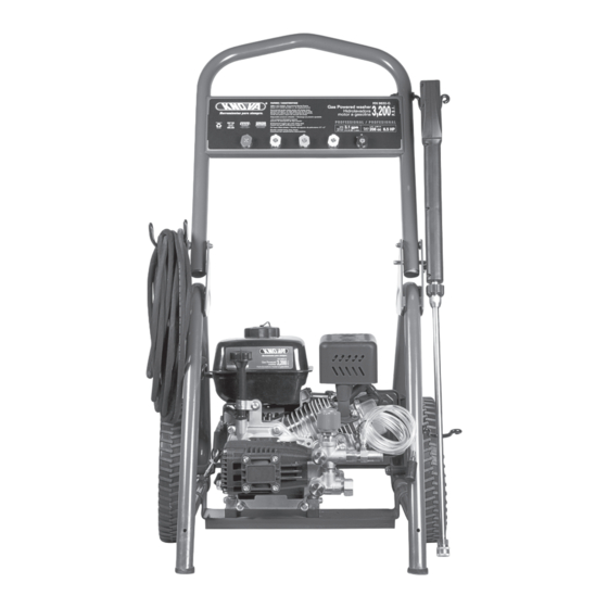
PRESSURE WASHER FEATURES A. Spray Tips - Store 5 spray tips here G. High Pressure Connection - Connection for high pressure B. High Pressure Hose - Extends 25 feet. hose. C. Fuel Tank - Check and fill with unleaded fuel here. H. -
Page 5: Important Safety Symbols
IMPORTANT SAFETY SYMBOLS This symbol indicates a potentially Indicates risk of explosion WARNING hazardous situation which could result in serious injury or death if not avoided. This symbol indicates a potentially Indicates risk of electric shock CAUTION hazardous situation which could result in damage to equipment or property. - Page 6 SAFETY INSTRUCTIONS WARNING WARNING Keep engine away from flammable objects and other hazardous Only use this unit as it is intended or serious injury or death materials. could result. • The fuel and its vapors used to power this unit are highly •...
-
Page 7: Assembly
ASSEMBLY ADDING / CHECKING ENGINE OIL (SEE FIG 2) WARNING • Place pressure washer on a level surface. • Remove one or both of the crankcase dipsticks to ensure you Do not attempt to assemble or operate this pressure washer do not overfill the engine. -
Page 8: Attaching Spray Gun
ASSEMBLY • Turn on water. CAUTION • Purge the system’s pump of air by releasing the safety and squeezing the trigger of the spray gun. Oil must be added to unit prior to first use. To avoid spillage, do not overfill fuel tank as gasoline expands. ATTACHING THE SPRAY GUN (SEE FIG 4 &... -
Page 9: Operation
OPERATION WARNING Engine Switch PRE-OPERATION CHECK LIST • Read and understand this operator manual in its entirety before operating pressure washer. • Check oil level and add oil to the proper level if low. Choke • Check fuel level and add fuel if needed. •... -
Page 10: How To Select Spray Nozzle
OPERATION USING AND SELECTING SPRAY TIPS RINSING WITH THE PRESSURE WASHER (SEE FIG 12 & 13) • Select and install appropriate spray tip as described earlier in • To connect or disconnect spray tip, pull back on the quick this manual. connect collar. -
Page 11: Maintenance
MAINTENANCE Regular maintenance will extend the life of this pressure washer CHECKING DETERGENT SIPHONING TUBE and improve its performance. The warranty does not cover • Check the detergent siphoning tube for clogs, leaks, or tears. items that result from operator negligence, misuse, or abuse. •... -
Page 12: How To Store
MAINTENANCE NOTAS WARNING Water pressure produced by this unit can cut through skin and tissue leading to serious injury and possible amputation. • Never attempt to repair high pressure hose, always replace. • Never attempt to repair leaks with sealant, always replace Oring or seal. -
Page 13: Troubleshooting
TROUBLESHOOTING PROBLEM CAUSE PROBLEM REMEDY SUGGESTED 1. Out of fuel Engine does not start 1. Fill fuel tank 2. Engine oil low 2. Add engine oil 3. Spark plug wire 3. Connect spark plug wire disconnected from spark plug 4. Bad spark plug 4. -
Page 14: List Of Parts Of Engine
LIST OF PARTS OF ENGINE model 1507A Number Description Part Number Description Part Quantity Quantity Valve Seat Pressure/Flow Adjusting Handle A1300101 A1200700 Pump Head Spring Plate (Upper) A1202320 A1300710 Shim A1202601 Retaining Ring A1300300 Thread Reducer A1201901 Set Screw L1000100 Plug A1202401 Spring (Compression) -
Page 15: Graph Of Parts Of Engine
GRAPH 0F PARTS OF ENGINE... -
Page 16: List Of Parts
LIST OF PARTS NOTAS Number Description Quantity FRAME (LOWER) 208CC ENGINE AXIAL PUMP WHEEL UPPER FRAME HANDLE GUN HOOK (UPPER) GUN HOOK (LOWER) HOOK (LOWER) HOSE STORAGE STRAP WHEEL AXLE RECOIL CORD LOOP RUBBER FOOT VIBRATION ISOLATOR UPPER FRAME PLUG HAIR PIN CARRIAGE BOLT (M6 X 50) M6 ACORN NUT... -
Page 17: Graph Of Parts
GRAPH 0F PARTS... -
Page 18: Lista De Partes
LISTA DE PARTES NOTAS Número Cantidad Nombre del Ítem MARCO (INFERIOR) MOTOR 208CC BOMBA AXIAL RUEDA MANIJA SUPERIOR DEL MARCO GANCHO PARA PISTOLA (SUPERIOR) GANCHO PARA PISTOLA (INFERIOR) GANCHO (INFERIOR) CUERDA DE GUARDADO DE LA MANGUERA EJE DE LA RUEDA ARO DE RETRACCIÓN DE LA CUERDA PIE DE GOMA AISLADOR DE VIBRACIONES... -
Page 19: Especificaciones
INDICE Especificaciones ..............17 Cómo utilizar la pistola atomizadora ......24 Cómo seleccionar la boquilla atomizadora ....25 Aplicaciones ................17 Mantenimiento ..............26 Reglas generales de seguridad ...........17 Mantenimiento de la Hidrolavadora ......26 Características de la Hidrolavadora ........19 Mantenimiento luego del uso ........26 Cambio del aceite ............26 Símbolos de seguridad ............20 Mantenimiento del motor ...........26 Instrucciones de seguridad ..........20... - Page 20 REGLAS DE SEGURIDAD PARA LAS HERRAMIENTAS ELECTRICAS 14. CUIDE SU HERRAMIENTA. Mantenga sus herramientas 21. USE LOS ACCESORIOS RECOMENDADOS. Consulte el afiladas y limpias para un desempeño mejor y más seguro. Siga manual del propietario para los accesorios recomendados. El las instrucciones para lubricación y cambio de accesorios.
-
Page 21: Características De La Hidrolavadora
CARACTERÍSTICAS DE LA HIDROLAVADORA A- Puntas del atomizador - Guarde 5 puntas de atomizador aquí Neumáticos nunca necesitan aire. B - Manguera de alta presión - Se extiende 7.5 m. G - Conexión de alta presión - Conexión para manguera de alta C - Tanque de combustible - Verifique y llene con combustible presión. -
Page 22: Símbolos De Seguridad
SÍMBOLOS DE SEGURIDAD IMPORTANTES Este símbolo indica una situación Indica riesgo de explosión. PELIGRO potencialmente peligrosa que puede resultar en heridas serias o la muerte si no se evita. Este símbolo indica una situación Indica riesgo de electrocución. PRECAUCIÓN potencialmente peligrosa puede resultar en daños a equipo o propiedad. - Page 23 INSTRUCCIONES DE SEGURIDAD PELIGRO PELIGRO Mantenga el motor lejos de objetos inflamables y otros Nunca opere esta unidad si hubiera partes averiadas o faltantes materiales peligrosos. y utilice únicamente repuestos Power Plus específicamente diseñados para esta unidad. • El combustible y sus vapores utilizados para poner en •...
-
Page 24: Ensamblaje De La Hidrolavadora
ENSAMBLAJE AGREGAR/VERIFICAR ACEITE DEL MOTOR (VER FIGURA 2) PELIGRO • Coloque la hidrolavadora sobre una superficie nivelada. • Quite una o ambas varillas del cárter para asegurarse de no No intente ensamblar u operar esta hidrolavadora hasta que llenar excesivamente el motor. usted haya leído y comprendido el manual completo. -
Page 25: Colocación De La Pistola Atomizadora
ENSAMBLAJE cierre. PRECAUCIÓN • Abra la canilla del agua • Purgue la bomba del sistema de aire liberando el seguro y Debe agregarse aceite a la unidad antes del primer uso. Para evitar derrames, no llene en exceso el tanque de combustible dado que la gasolina se expande. -
Page 26: Operación
OPERACIÓN LISTA DE VERIFICACIÓN PRE OPERACIÓN • Para evitar la inercia, tire del cordón de encendido lentamente • Lea y comprenda este manual en su totalidad antes de operar hasta que sienta una resistencia, luego tire rápidamente. la hidrolavadora. • Verifique el nivel de aceite y agregue aceite para que llegue a nivel apropiado si estuviera bajo. -
Page 27: Cómo Seleccionar La Boquilla Atomizadora
OPERACIÓN UTILIZACIÓN Y SELECCIÓN DE PUNTAS ATOMIZADORAS ENJUAGANDO CON LA HIDROLAVADORA (VER FIGURAS 12 y 13) Seleccione e instale la punta atomizadora apropiada tal como se Para conectar o desconectar una punta atomizadora, retire el describe con anterioridad en este manual. aro de conexión rápida. -
Page 28: Mantenimiento
MANTENIMIENTO Un mantenimiento regular extenderá la vida de esta hidrolavadora VERIFICACIÓN DEL TUBO SIFÓN DE DETERGENTE y mejorará su funcionamiento. La garantía no cubre situaciones • Verifique que el tubo sifón de detergente no esté obstruido, que resultaran de la negligencia del operador, el mal uso o el desgarrado o perforado. -
Page 29: Cómo Guardar
MANTENIMIENTO NOTAS PELIGRO La presión de agua producida por esta unidad puede cortar a través de la piel y el tejido produciendo serias heridas y posibles amputaciones. • Nunca intente reparar una manguera de alta presión, siempre reemplácela. • Nunca intente reparar pérdidas con sellador, reemplace siempre el anillo sellador o sello. -
Page 30: Resolución De Problemas
SOLUCIÓN DE PROBLEMAS CAUSA PROBLEMA SOLUCIÓN 1. No tiene combustible El motor no enciende 1. Llene el tanque de combustible 2. Poco aceite de motor 2. Agregue aceite de motor 3. El cable de la bujía está 3. Conecte el cable de la bujía. desconectado de la bujía 4. -
Page 31: Lista De Partes De Motor
LISTA DE PARTES DE MOTOR modelo 1507A Clave Number Description No. de Parte Cantidad Description Part Quantity Manija de ajuste de presión/flujo A1300101 Asiento de válvula A1200700 Hoja de resorte (superior) A1202320 A1300710 Cabeza de bomba A1202601 Anillo de retención A1300300 Calce A1201901... -
Page 32: Gráfico De Partes De Motor
GRAFICO DE PARTES DE MOTOR modelo 1507A... - Page 33 NOTES...
Need help?
Do you have a question about the KN 9832-G and is the answer not in the manual?
Questions and answers