Table of Contents

Related Manuals for AERMEC VED I US 430


Summary of Contents for AERMEC VED I US 430
- Page 1 MANUAL INSTALLATION - INSTALLATION MANUELLE VED_I Fan coils - Ventilo-convecteurs • Duct installation - Installation de conduits 220V/1/60HZ pag.5 pag.18 IVED_ITI 150. - 4880990_00...
- Page 2 10 years for any further reference. AERMEC S.p.A. declines all responsibility for any damage due to Read all of the information contained in this manual carefully improper use of the machine, partial or hasty reading of the infor- and completely.
- Page 3 TRASPORTO • TRANSPORT • TRANSPORT • TRANSPORT • TRANSPORTE NICHT nass machen. NON bagnare. Tenere al KEEP DRY. Keep out of NE PAS mouiller. Tenir à NO mojar. Conservar Vor Regen geschützt riparo dalla pioggia. the rain. l’abri de la pluie. protegido de la lluvia.
-
Page 4: During Operation
IMPORTANT INFORMATION inside the device due to the heat expan- AND MAINTENANCE DO NOT USE WATER THAT IS TOO HOT sion of the elements (plastic and metal), Use soft cloths or sponges soaked in warm however, this does not indicate a fault and water (no higher than 40 °C/104°F) to clean does not cause damage to the unit unless ATTENTION:... -
Page 5: Product Identification
PRODUCT IDENTIFICATION AERMEC fan coils can be identified through: example of technical plate example of packaging label PACKAGING LABEL Located on the packaging, it contains the xxxxxxxxxx product identification details. Volt TECHNICAL PLATE Located inside the unit, it indicates the identification and technical data of the product. -
Page 6: Description Of The Unit
DESCRIPTION OF THE UNIT The fan coils, designed to adapt to any particular, the fact that the unit can be sories up to the management of the VED_I requirement in ducted systems, are units integrated in the VMF system allows you to inserted in complex networks of fan coils that cannot be accessed by the public. -
Page 7: Main Components
The electric motor is isolated with elastic effect sensors” and the control system used the following versions: supports. by the AERMEC VED fan coil units provide with 3 rows and with 4 rows; the most sophisticated mechanical and 3 rows with hot water-operated 2-row coil... -
Page 8: Selection Criteria
SELECTION CRITERIA The VED_I_US wall-ceiling mounted fan and cooling) and 1 - 2-row coils (heating coils are suitable for both vertical and hor- only) are shown in the charts. izontal ducted installations. The correction factors in functioning with VED_I_US is designed to operate at the 3 glycol water in cooling and heating modes default speeds described in the manual. -
Page 9: Operating Limits
OPERATING LIMITS VED_I 430US 440US 530US 540US 432US 441US 532US 541US Maximum water inlet temperature °C -°F 80 - 176 Maximum water inlet temperature recommended °C -°F 65 - 149 Maximum operating pressure bar - PSI 8 - 72.52 Minimum water flow rate (Main coil) 3000 3000 3000... - Page 10 ACCESSORIES DUCTING ACCESSORIES: RDA_VUS STRAIGHT INTAKE FITTING Straight intake fitting with rectangular flange for ducting. Made of galvanised sheet steel. It can house the air filter. DIMENSIONS Mod. RDA450V 1053 41.46 257 10.12 RDA670V 1453 51.20 308 12.13 RPA_VUS INTAKE PLENUM WITH RECTANGULAR FLANGE RPA_VUS is an intake plenum with rectangular flange made of galvanised sheet steel.
- Page 11 RPM_VUS FLOW PLENUM WITH RECTANGULAR FLANGE RPM_V is a flow plenum with rectangular flange made of galvanised sheet steel and fully insulated. This accessory is for connection of a channel with a rectangular section to the flow vent of the unit. According to requirements, the RPM_V accessory allows for both longitudinal and perpendicular delivery to the air flow passing through the unit.
-
Page 12: Installing The Unit
INFORMATION REGARDING INSTALLATION to specific requirements, is left to the T h e V E D _ I _ U S u n i t i s s et u p fo r ATTENTION: make sure that the power experience of the installer. connections with air ducts. -
Page 13: Hydraulic Connections
HYDRAULIC CONNECTIONS - Make the hydraulic connections. ATTENTION: Always use a wrench and counter-wrench to fix the pipes. The position, type and diameter of the hydraulic connections are specified in the dimensional data. It is recommended to insulate water pipes and/or to install the suitable auxiliary condensate collection tray, available as an accessory, in order to avoid dripping... -
Page 14: Condensate Drain
CONDENSATE DRAIN The fan coil tray has 2 condensate drains is advisable to make a siphon which on the right and left side. We recommend prevents odours from returning into using the condensate drain fitting on the environment. Run an operating and the side of the hydraulic connections. -
Page 15: Alarm Code
ALARM CODE This section is reserved to the After-sales Service Centres only. The board is found inside the unit and requires disassembly. DANGER! Only qualified mainte- nance personnel can access it. On the Inverter board there are 2 LED (Alarm/Power) indicating the functioning status of the unit. - Page 16 DIP SWITCH SETTING - only for units with ducted installation In ducted installations, to allow adjusting the maximum speed in the VED I fan coils. To Attention!: Follow the settings indicated in static pressure provided by the fan coil to increase fan speed, modify the settings of the table for each size of VED I.
-
Page 17: Problems And Solutions
VED_I 430US 440US 530US 540US 441US 532US 541US Ø 3/4"G 3/4"G 3/4"G 3/4"G 3/4"G 3/4"G 3/4"G Water connections main battery (female) Ø 1/2"G 1/2"G 1/2"G Water coil for heating only (female) 20,5 20,5 20,5 20,5 20,5 20,5 20,5 Attacks condensate drain (outside diameter) 0,81 0,81 0,81... -
Page 18: Pendant Le Fonctionnement
INFORMATIONS IMPOR- une sensation de froid et être gênant. chauffage, on peut entendre un léger bruis- sement d'air près du ventilo-convecteur. TANTES ET ENTRETIEN NE PAS UTILISER DE L'EAU TROP CHAUDE Parfois le ventilo-convecteur peut émettre Pour nettoyer le ventilo-convecteur utiliser des odeurs désagréables dues à... - Page 19 IDENTIFICATION DU PRODUIT AERMEC ventilo-convecteurs peuvent être exemple de plateau technique exemple de étiquette de l'emballage identifiés par: EMBALLAGE LABEL xxxxxxxxxx Situé sur l'emballage, il contient du Volt les détails d'identification du produit. PLAQUE TECHNIQUE Situé à l'intérieur de l'appareil, il indique les données d'identification et techniques...
-
Page 20: Description De L'unite
DESCRIPTION DE L’UNITE Le ventilo-convecteur est une unité ter- toutes les exigences des installations cana- ventilo-convecteur individuel avec acces- minale servant au traitement de l’air d’un lisées. soires à la gestion de l'unité VED_I insérée milieu tant en hiver qu’en été. Les ventilo- En particulier, la possibilité... -
Page 21: Composants Principaux
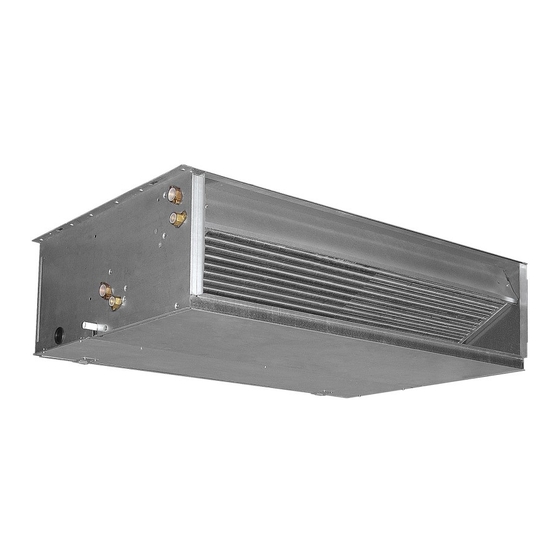
COMPOSANTS PRINCIPAUX Exemple: VED_I532US 1 Flanc droit (structure portante) 6 Évents/conduits d'évacuation sur la batterie 10 Ventilateur centrifuge 2 Bride de soufflage de l'air 7 Raccordements hydrauliques 12 Armoire électrique du moteur électrique 3 Batterie d'échange thermique 8 Évacuation des condensats 13 Moteur électrique 4 Bac de récupération des condensats/ 9 Rainures pour la fixation... - Page 22 LES CRITÈRES DE SÉLECTION Les ventilo-convecteurs montés VED_I_US Les rendements de refroidissement sen- plafond monté sur la base du taux de flux mur-plafond sont adaptés pour les instal- sibles et le total à la vitesse maximale d'air et la vitesse du ventilateur, sont pré- lations avec conduits verticaux et horizon- en fonction de la température de l'eau sentés sous forme de tableau, les courbes...
- Page 23 OPERATING LIMITS VED_I 430US 440US 530US 540US 432US 441US 532US 541US La température maximale d'entrée d'eau °C -°F 80 - 176 La température d'entrée d'eau maximale recommandée °C -°F 65 - 149 bar - Pression de service maximale 8 - 72.52 Débit minimal d'eau (bobine principale) 3000 3000...
- Page 24 ACCESSOIRES POUR CANALISATION : RDA_VUS RACCORD DROIT D'ASPIRATION Raccord d'aspiration droit avec bride rectangulaire pour canalisation. En tôle galvanisée. Il peut loger le filtre à air. DIMENSIONS Mod. RDA450V 1053 41.46 257 10.12 RDA670V 1453 51.20 308 12.13 RPA_VUS PLENUM D'ASPIRATION AVEC BRIDE RECTANGULARE RPA_VUS est un plenum d'aspiration avec bride rectangulaire, réalisé...
- Page 25 RPM_V PLENUM DE REFOULEMENT AVEC BRIDE RECTANGULAIRE RPM_V est un plenum de soufflage avec bride rectangulaire, réalisé en en tôle galvanisée, avec isolation interne. Cet accessoire permet de raccorder le canal de section rectangulaire à la bouche de soufflage de lunité VED_I. L'accessoire RPM_V permet le soufflage longitudinal et perpendiculaire au flux d'air qui traverse l'unité...
-
Page 26: Installation De L'unité
INFORMATIONS POUR L'INSTALLATION Nous laissons toutefois à l'installateur et à avec des canalisations d'air. ATTENTION : avant d'effectuer une son expérience le soin de perfectionner Les ventilo-convecteurs sont équipés de quelconque intervention, vérifier si l'ali- toutes les opérations en fonction des exi- moteurs à... -
Page 27: Raccordements Hydrauliques
RACCORDEMENTS HYDRAULIQUES - Effectuer les raccordements hydrauliques. ATTENTION : Utiliser toujours une clé et une contre-clé pour fixer les tuyaux. La position, le type et le diamètre des rac- cordements hydrauliques sont reportés dans les données dimensionnelles. Il est conseillé d'isoler de manière appro- priée les tuyaux de l'eau et/ou d'instal- ler le bac auxiliaire de récupération des condensats prévu, disponible comme... - Page 28 ÉVACUATION DES CONDENSATS Le bac du ventilo-convecteur dispose de à garder tout au long du parcours une deux raccords d'évacuation (côté droit et inclinaison appropriée (min. 1 %). côté gauche). Si l'évacuation se fait dans les égouts, il est Il est conseillé d'utiliser le raccord conseillé...
- Page 29 CODIFICATION DES ALARMES Cette section est réservée aux centres d'assistance. La carte se trouve à l'intérieur de l'unité et demande à ce que celle-ci soit démon- tée. DANGER ! Il n'y a que le personnel prépo- sé à la maintenance qui peut y accéder. Sur la carte de l'Inverseur il y a 2 diodes (Alarm / Power) qui signalent l'état de fonctionnement de l'unité.
- Page 30 CONFIGURATIONS DU COMMUTATEUR DIP - uniquement pour les unités avec l’ins- tallation canalisée Dans les installations avec des canaux, maximale. Pour augmenter la vitesse de Attention !: S’en tenir aux configurations adapter la hauteur manométrique fournie ventilation, modifier les configurations des indiquées sur le tableau pour chaque taille par le ventilateur aux pertes de charge du commutateurs dip placés sur le moteur et...
-
Page 31: Problèmes Et Solutions
VED_I 430US 440US 530US 540US 441US 532US 541US Ø 3/4"G 3/4"G 3/4"G 3/4"G 3/4"G 3/4"G 3/4"G Branchements d'eau batterie principale (femelle) Ø 1/2"G 1/2"G 1/2"G Bobine de l'eau pour chauffage seul (femelle) 20,5 20,5 20,5 20,5 20,5 20,5 20,5 Attaques vidange condensat (diamètre extérieur) 0,81 0,81 0,81... - Page 32 DIMENSIONS (INC) VED_I: 430 - 440 - 530 - 540 - 441 - 532 - 541 US 61,67 60,35 13,82 1,57 0,59 1,57 12,09 1,81 4,26 9,72 11,30 12,83 59,29 59,41 DIMENSIONS (INC) VED_I 630 - 640 - 730 - 740 - 632 - 641 - 732 - 741 US 46,02 44,61 11,81...
- Page 33 SCHEMI ELETTRICI • WIRING DIAGRAMS • SCHEMAS ELECTRIQUES • SCHALTPLÄNE • ESQUEMAS ELÉCTRICOS VED_I430_741US SCHEMA DI COLLEGAMENTO MOTORE MOTOR CONNECTION DIAGRAM SCHEMA DE RACCORDEMENT MOTEUR ANSCHLUSSPLAN MOTOR ESQUEMA DE CONEXIONADO ELÉCTRICO DEL MOTOR BIANCO GRIGIO MARRONE NERO ROSSO VIOLA GIALLO VERDE ROSA WHITE...
- Page 36 AERMEC S.p.A. si riserva la facoltà di apportare in qualsiasi momento tutte le modifiche ritenute necessarie per il miglioramento del prodotto. Les données mentionnées dans ce manuel ne constituent aucun engagement de notre part. Aermec S.p.A. se réserve le droit de modifier à tous moments les données considérées nécessaires à...
Need help?
Do you have a question about the VED I US 430 and is the answer not in the manual?
Questions and answers