Table of Contents
Advertisement
Quick Links
This document applies to Product
Version History:
S. No.
Version No.
1
2
3
The information contained in this document is copyright, and
shall not be reproduced without the written authority of EMS
EMS827
AMF Genset Controller
User Manual
Build Version
Firmware Version
Changes Made
Date Modified
www.ems.gen.nz
©2010
9001-xxxx
3600-xxxx
5000-xxxx
Modified By
Approved By
Advertisement
Table of Contents

Subscribe to Our Youtube Channel
Related Manuals for EMS EMS827


Summary of Contents for EMS EMS827
- Page 1 Build Version 3600-xxxx Firmware Version 5000-xxxx Version History: S. No. Version No. Changes Made Date Modified Modified By Approved By www.ems.gen.nz The information contained in this document is copyright, and shall not be reproduced without the written authority of EMS ©2010...
-
Page 2: Table Of Contents
EMS 827 GENSET CONTROLLER Contents Introduction ..........................4 Benefits ............................. 4 Physical Form ..........................5 Functions ........................... 6 System ..........................6 Engine Monitoring ....................... 6 Generator Monitoring ......................8 Mains AC Monitoring ......................8 System LED Indications ......................8 Transfer Control LED Indications ................... 9 System LCD Displays ...................... - Page 3 EMS 827 GENSET CONTROLLER 12.12 Room Temp Column ......................43 12.13 Aviation Light Column (Not protected against prolonged power loss) ........43 12.14 I/O Config Column ......................43 12.15 Comms (Communications) Setup Column................45 12.16 Log Viewer Column......................45 Communications ........................46 13.1...
-
Page 4: Introduction
EMS 827 GENSET CONTROLLER EMS827 AMF Controller for 30KVA to 160KVA Gensets 1. Introduction The unit is a controller for mid-engine Gensets with Automatic Mains Failure (AMF) functionality sold in the private market segment. The unit incorporates Manual, Autostart Start and AMF Autostart initiated start and stop sequencing, monitors engine and alternator operating parameters and provides both engine and alternator protection, in a single integrated package. -
Page 5: Physical Form
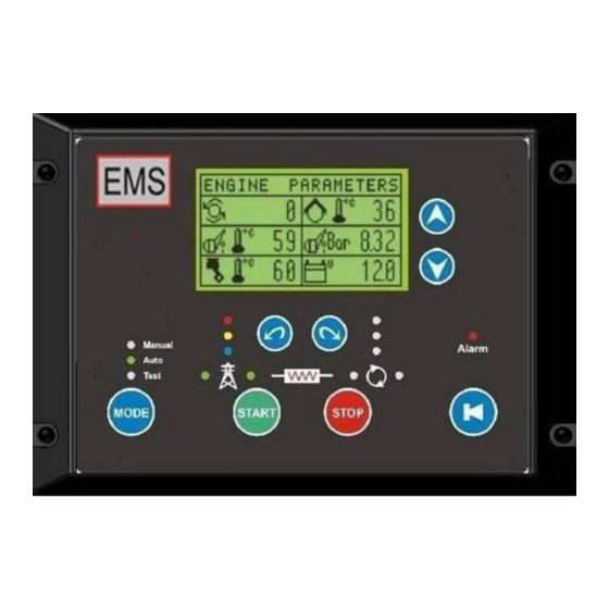
EMS 827 GENSET CONTROLLER 3. Physical Form Front View Rear View Confidential www.ems.gen.nz Page 5... -
Page 6: Functions
EMS 827 GENSET CONTROLLER 4. Functions 4.1 System Function Description Protection Shutdown Automatic preventative engine and genset shutdown in the event of abnormal operating conditions with optional configuration parameters and clear LCD status messages Manual Start In response to the front panel pushbutton, the unit performs a fully... - Page 7 EMS 827 GENSET CONTROLLER Function Description Lubrication Oil Pressure Monitors engine oil pressure with optional configuration parameters and clear LCD status messages this ensures the oil pressure remains within configured limits. Exceeding these limits will result in automatic engine shutdown to prevent damage. Oil pressure monitoring can be from an oil pressure switch, or a resistive oil pressure sensor, or both.
-
Page 8: Generator Monitoring
EMS 827 GENSET CONTROLLER 4.3 Generator Monitoring Function Description AC Phase Voltage Monitors 1, 2 or 3 phases of AC voltage with optional configuration parameters and clear LCD status messages. Measurements include L-N and L-L. AC Phase Current Monitors 1 or 3 Delta phases of AC current with optional configuration parameters and clear LCD status messages. -
Page 9: Transfer Control Led Indications
EMS 827 GENSET CONTROLLER Function Description Auto Mode Green LED indication that the unit is in Automatic Start Mode Test Mode Green LED indication that the unit is in Test Mode 4.6 Transfer Control LED Indications Function Description Alternator Phase Red LED indication that the Alternator phase 1 voltage is available. -
Page 10: Ac Inputs
EMS 827 GENSET CONTROLLER 4.8 AC Inputs Function Description 3 Phase Mains AC Voltage Mains AC voltages. 3 Phase Alternator AC Alternator AC voltages. Voltage 3 Phase Alternator Current Alternator AC currents via external 5A CTs. 4.9 Analog Inputs Function... -
Page 11: Outputs
EMS 827 GENSET CONTROLLER Function Description Close to common. Current limited 10mA at 10V Digital Input 3 Configurable. Default = Fire. Shutdown genset and open both contactors. Close to common. Current limited 10mA at 10V Digital Input 4 Configurable. Status, Warning, Alarm, PC programmed message. -
Page 12: Operation
EMS 827 GENSET CONTROLLER 5. Operation Front Layout 5.1 Buttons Button Function Description Mode button Used to change mode between manual, auto and test MODE Start button / Menu Previous 1. Used to initiate generator start sequence START 2. Used as system menu previous button Stop button / Menu Next 1. -
Page 13: Leds
EMS 827 GENSET CONTROLLER Button Function Description Mains Transfer Button Used to start transfer sequence of load from genset to mains Genset Transfer Button Used to start transfer sequence of load from mains to genset Screen Scroll up / Setup menu up Button 1. -
Page 14: Initial Power Up
EMS 827 GENSET CONTROLLER Button Function Description Mains Supply Phase Status Indicates the phases which are available from the mains 1. Red – Phase 1 2. Yellow – Phase 2 3. Blue – Phase 3 Manual Mode Indicates that the system is in manual mode... -
Page 15: Manual Operation
EMS 827 GENSET CONTROLLER In MANUAL mode the unit responds only to the manual push button and may control A and B contactors if these options have been enabled. In the AUTO mode, the unit responds to the autostart input or Remote Starts and controls A and B contactors. -
Page 16: To Stop The Genset
EMS 827 GENSET CONTROLLER o Allows the engine to stabilise at full speed before going on load. Oil pressure and Over-speed are monitored. The display shows ‘Warm Up’ with a countdown time. RUNNING The display shows ‘Running’. Operating parameters are scrolled onto the display. -
Page 17: Display Operation
EMS 827 GENSET CONTROLLER The unit cranks the engine for the crank time or until the engine fires. If the engine does not fire after the crank time, then the unit will repeat the crank procedure after waiting for the crank rest time. This cycle is repeated for the “Crank Retries”... - Page 18 EMS 827 GENSET CONTROLLER Screen – 1 Screen – 2 Screen - 3 Screen – 4 Screen – 5 Screen – 6 Confidential www.ems.gen.nz Page 18...
- Page 19 EMS 827 GENSET CONTROLLER Screen – 7 Screen – 8 Screen – 9 Screen – 10 Screen – 11 Screen – 12 Confidential www.ems.gen.nz Page 19...
- Page 20 EMS 827 GENSET CONTROLLER Screen – 13 Screen – 14 Screen – 15 Screen – 16 Screen – 17 Screen – 18 Confidential www.ems.gen.nz Page 20...
-
Page 21: Alarms And Warnings
EMS 827 GENSET CONTROLLER Screen – 19 Then returns to start scroll If Warnings or Alarms are present, the associated messages are included in the LCD scroll list, and are shown after the last screen has been displayed. 7. Alarms and Warnings In the event of abnormal operating conditions the unit will issue a warning or an alarm and shut the genset down as required. - Page 22 EMS 827 GENSET CONTROLLER Message Function description Replenish the fuel. The Fuel Level is unexpectedly going down while the genset is not Fuel Loss running The battery voltage went above the setpoint. High battery voltage usually indicates that the battery charging...
- Page 23 EMS 827 GENSET CONTROLLER Message Function description Check the Fuel Level Sensor and associated wiring. The Speed Sensing system is not working as expected. Check the associated speed sensor wiring and external influences Speed Fault such as poorly operating battery chargers and poorly filtered UPS systems connect to the load.
- Page 24 EMS 827 GENSET CONTROLLER Message Function description Check for over loading. Check cooling air flows, Check coolant level. The Canopy Temperature went above the alarm setpoint. Canopy Temp High Check cooling air flows. Check for overloading. The Fuel Level is below the alarm setpoint.
- Page 25 EMS 827 GENSET CONTROLLER Message Function description Check the canopy temperature sensor and associated wiring. The Fuel Level Sensor is not functioning as expected. Fuel-L Fault Check the Fuel Level Sensor and associated wiring. The Speed Sensing system is not working as expected.
-
Page 26: Inputs Electrical Specification
EMS 827 GENSET CONTROLLER Message Function description AGF Phase Reversal The generator has a phase reversal or the wiring is incorrect AGF Low V1 Volts Voltage on Alternator Phase V1 is Low AGF Low V2 Volts Voltage on Alternator Phase V2 is Low... - Page 27 EMS 827 GENSET CONTROLLER Input Type Comment Digital Input 1 Digital Suitable for switch input. Connect to 0V = Active Digital Input 2 Digital Suitable for switch input. Connect to 0V = Active Digital Input 3 Digital Suitable for switch input. Connect to 0V = Active...
-
Page 28: Outputs Electrical Specification
EMS 827 GENSET CONTROLLER Input Type Comment Speed A magnetic pickup input 3V – 70V peak at >500 to 10KHz Voltage Speed A Battery Alternator input 2V to 70V peak at 20Hz to 1KHz Speed B magnetic pickup input 3V – 70V peak at >500 to... -
Page 29: Load Transfer And Contactor Operation
EMS 827 GENSET CONTROLLER 8. Load Transfer and Contactor Operation The unit provides for both Mains and Generator contactor control even though in many applications this function will not be used, instead an MCB is used to switch the generator to and from the load. -
Page 30: Generator
EMS 827 GENSET CONTROLLER Cal Value = (Freq x 600) / RPM. Eg: (100Hz x 600) / 1500 = 40 Enter the number 40 9.3 Generator If the unit is used in a genset application the speed source can be the generator 50/60 Hz output and is connected internally within the unit from the AC input connectors. -
Page 31: Battery Charging Alternator Excitation
EMS 827 GENSET CONTROLLER Calculate Speed Calibration value as follows: Cal Value = (Freq x 600) / RPM. Eg: (257Hz x 600) / 1500 = 102.8. Enter the number 103. 10. Battery Charging Alternator Excitation The battery charging alternator excitation system is implemented using a burst mode pulse system. -
Page 32: Set-Up
12. Set-up In the factory environment the unit can be setup by the EMS Cloning Utility or by the EMS Windows setup utility. In the field, adjustments to the unit can be made using the buttons on the front panel. -
Page 33: System Column
EMS 827 GENSET CONTROLLER 12.2 System Column Item Range Default Description Contrast 0 - 13 LCD Contrast Display Cycle Time, sets frequency of display update. If set to Off, display scrolling is disabled. 2 – 60 Disp Update For manual scrolling press the... - Page 34 EMS 827 GENSET CONTROLLER Item Range Default Description U Spd Wrn 400 – 3600 Warning threshold for slow engine speed U Spd Alm 400 – 3600 Alarm threshold for slow engine speed O Spd Wrn 400 – 4000 1600 Warning threshold for high engine speed O Spd Alm 400 –...
- Page 35 EMS 827 GENSET CONTROLLER Item Range Default Description Selects type of oil sensor being used. 0 – 90 Oil Type 0 – 90 Dual station sensors can be used on same analog 10 – 180 input. 5, 7.5, 10 Oil Range Used to select the oil sensor full scale in Bar 0.2 - 3.0...
- Page 36 EMS 827 GENSET CONTROLLER Item Range Default Description Selects Engine temperature sensor type. COF = Switch: Close on Fault TS120 ETemp Type TS150 TS120 = Sensor with FSD of 120ºC TS150 TS150 = Sensor with FSD of 150ºC TS200 TS200 = Sender with FSD of 200ºC 70 –...
- Page 37 EMS 827 GENSET CONTROLLER Item Range Default Description Lo Battery 9.5 – 24 10.0 Low Battery voltage level warning Volts 12 – 32 Hi Battery 15.0 High Battery voltage level warning Volts 12.0 – Maximum Battery Voltage. If the Battery voltage 38.0...
-
Page 38: Timers Column
Stop on Alarm Off should only be chosen for mission critical applications when shutdown is not permitted and the engine can run to destruction. This option is only settable using the EMS Windows setup utility. 12.4 Timers Column Item... -
Page 39: Contactor A Column
EMS 827 GENSET CONTROLLER Item Range Default Description Sounder remains indefinitely until 0 – 600 acknowledged Sounder Time Value = Sounder maximum time is the value in seconds. Maintenance 50 – 1000 Hours between Maintenance Requests 12.5 Contactor A Column... -
Page 40: Ac Setup Column
EMS 827 GENSET CONTROLLER Item Range Default Description Units for the Autostart delay time Start Units Sec = Seconds Min = Minutes Selects the time for which the Autostart has to be 1 – 600 StartRestor restored before the start delay timer is reset and starting aborted. -
Page 41: Amf Setup Column
EMS 827 GENSET CONTROLLER 12.8 AMF Setup Column Item Range Default Description 60 – 240 The minimum voltage below which the Genset is Low Volt Trip started Volts 110 – 300 The maximum voltage above which the Genset is Hi Volt Trip... -
Page 42: Testing Column
EMS 827 GENSET CONTROLLER Item Range Default Description AMPS CapType The type of capacity units used for the Genset. Selects the full load capacity of the generator in units Capacity 10 – 6553 of CapType 10 – 150 Selects the trip point for the overload contact as a... -
Page 43: Room Temp Column
EMS 827 GENSET CONTROLLER 12.12 Room Temp Column Item Range Default Description Enable Enables room temperature control. 1 - 60 Trip Room temperature trip level. °C 1 - 60 Restore Room temperature restore level. °C 12.13 Aviation Light Column (Not protected against prolonged power loss) - Page 44 EMS 827 GENSET CONTROLLER Item Range Default Description Fire Alarm = Stop the engine when sensor is activated BeltBreak Door = Alarm when door is opened, engine is not I/P2 FireAlarm FireAlarm stopped Door Bypass = Inhibit all engine start and stop sequencing...
-
Page 45: Comms (Communications) Setup Column
Modem = Uses RTS/CTS flow control. 5 wire connection. Modem Dial Allocates the phone number for alarm dial out 1 - 5 12.16 Log Viewer Column Fault history log items cannot be deleted or changed except by using the EMS Windows setup utility program. Item Range Default Description... -
Page 46: Communications
EMS 827 GENSET CONTROLLER These logs captures fuel replenishments by start and finish % values. The values are indexed to Fuel Log the run hour’s value. Logging occurs on fuel reduction when the engine is not running and fuel increase at all times. - Page 47 EMS 827 GENSET CONTROLLER Feature Specification Opto-coupler isolated. Whetting current 10mA at 12 V DC. Digital Input Rating DC input protection for +/- 30V DC Transient Protected. Current limited outputs approx 15mA or less as required by sensors/ Analog Input Rating Short circuit and reverse voltage protected.
- Page 48 EMS 827 GENSET CONTROLLER Feature Specification Terminations Amp DUAC / Molex Mini Fit JNR Environmental Tests: IEC68 Part2 Testing EMC Compliance: EN50081-1, EN50081-2, IEC6100-4-3 Electrical Safety AS 3100 and AS 3260 Confidential www.ems.gen.nz Page 48...
-
Page 49: Installation And Wiring
EMS 827 GENSET CONTROLLER 14. Installation and Wiring NB: The unit is a complex electronic device and caution should be taken to ensure correct wiring before power is applied. The unit is fitted with 2, 3, 8 and 14 way Molex Minifit or equivalent socket connectors for which mating plugs can be selected from the Amp PE, or TPK range. - Page 50 EMS 827 GENSET CONTROLLER Connector Assignment Connection Information Connection J2: DC Power Supply Common –ve. (Note 1) Battery +ve. (Note 2) Connection J3: Speed Input Speed Input A Speed Input B Speed Common J4: Alternator AC Input Connection Alternator AC Phase 1 (Red)
- Page 51 EMS 827 GENSET CONTROLLER Connector Assignment Connection Information Oil Pressure Input Oil Temperature Input Auto Start Input Emergency Stop Input Oil Pressure Switch Input I/P1 VBelt Input I/P2 Bypass Input I/P4 Canopy Door Input I/P3 Fire Alarm Input I/P5 User Definable Input...
-
Page 52: Trouble Shooting
EMS 827 GENSET CONTROLLER 1. This connection must be made directly to the engine crankcase for lowest electrical noise. This connection must not have currents other than the controller currents flowing and must be used exclusively for the controller. 2. This connection must be made directly to the positive terminal of the battery for best performance. - Page 53 EMS 827 GENSET CONTROLLER The unit has detected that the engine temperature has not risen to 50 degrees within the first 5 minutes of running or the temperature Engine Temp Flt sensor has shorted to common. Normally this indicates a faulty temperature sender or broken wiring.
- Page 54 EMS 827 GENSET CONTROLLER The Oil Pressure has dropped below the Oil Pressure Warning set Low Oil Pressure point while the engine is running. The Oil Pressure Icon is lit. Engine temperature has exceeded the high temperature warning set High Engine Temp point after the Temperature monitoring delay has expired.
-
Page 55: Wiring Options
EMS 827 GENSET CONTROLLER 16. Wiring Options Crankcase Crankcase Crankcase Crankcase Crankcase Crankcase Crankcase Temperature Sensing Options Oil Pressure Sensing Options Side Mounting Top Mounting Water Level Probe Water Level Radiator Probe T op Radiator Side Crankcase Crankcase Note: The radiator must be electrically bonded to the crankcase common. - Page 56 EMS 827 GENSET CONTROLLER Typical Contactor Control 1. Engine Sensor Tables PowerTech Oil Pressure Sensor Pressure in Ohms 0-90 Oil Pressure Sensor Pressure in Ohms Confidential www.ems.gen.nz Page 56...
- Page 57 EMS 827 GENSET CONTROLLER 10-180 Oil Pressure Sensor Ohms Pressure in BAR PowerTech Engine Temperature Sensor Ohms Temperature 199.2 166.6 132.5 119.7 116.6 TS120 Engine Temperature Sensor Ohms Temperature 287.4 112.6 95.2 80.9 69.1 51.2 44.3 38.5 33.6 29.4 25.8 22.7...
- Page 58 EMS 827 GENSET CONTROLLER TS150 Engine Temperature Sensor Ohms Temperature 322.8 179.5 112.5 62.2 48.1 36.5 28.9 23.1 18.6 TS200 Engine Temperature Sensor Ohms Temperature 151.2 65.5 51.2 40.3 32.2 25.8 23.3 21.1 17.3 16.6 EMS08 Room Temperature Sensor Ohms Temperature 276.3...
- Page 59 EMS 827 GENSET CONTROLLER 0-90 Fuel Level Sensor Fuel Level Ohms 10-180 Fuel Level Sensor Fuel Level Ohms 10-180 Fuel Level Sensor Fuel Level Ohms Confidential www.ems.gen.nz Page 59...
- Page 60 EMS 827 GENSET CONTROLLER EMS820 Fuel Level Sensor Ohms Fuel Level % 195.2 188.6 148.5 127.8 106.8 64.8 43.8 20.9 Fuel Level in Setup Menu (Default values) Fuel Level Ohms Confidential www.ems.gen.nz Page 60...
Need help?
Do you have a question about the EMS827 and is the answer not in the manual?
Questions and answers