Table of Contents
Advertisement
Quick Links
This document applies to:
Version History:
S. No.
Version No.
1
2
3
The information contained in this document is copyright, and
shall not be reproduced without the written authority of EMS
EMS372
GCU/3AS
Genset Controller
User Manual
Build version
Firmware Version
Changes Made
www.ems.gen.nz
9001-0104
3600-0168
5000-0046 (V3.G.3D)
Date Modified
©2008
Modified By
Approved By
Advertisement
Table of Contents

Subscribe to Our Youtube Channel
Related Manuals for EMS EMS372


Summary of Contents for EMS EMS372
- Page 1 3600-0168 Firmware Version 5000-0046 (V3.G.3D) Version History: S. No. Version No. Changes Made Date Modified Modified By Approved By www.ems.gen.nz The information contained in this document is copyright, and shall not be reproduced without the written authority of EMS ©2008...
-
Page 2: Table Of Contents
EMS 372 GENSET CONTROLLER Contents Introduction ..........................4 Benefits ............................. 4 Physical Form ..........................5 Functions ........................... 6 System ..........................6 Engine Monitoring ....................... 6 Generator AC Monitoring ..................... 7 Mains AC Monitoring ......................8 System LED Indications ......................8 System LCD Displays ...................... - Page 3 EMS 372 GENSET CONTROLLER 10.11 Comms (Communications) Setup Column................33 Communications ........................34 11.1 Unit General Specifications ....................34 Installation and Wiring ......................36 12.1 Connector Detail ....................... 37 Trouble shooting ........................38 Wiring Options ........................41 Engine Sensor Tables ......................42 Confidential www.ems.gen.nz...
-
Page 4: Introduction
Genset Controller 1. Introduction The EMS372 is a custom designed controller gensets sold in the private market segment. The unit incorporates both manual ,autostart and AMF(Automatic Mains Failure) initiated start and stop sequencing, monitors engine and alternator operating parameters and provides both engine and alternator protection, in a single integrated package. -
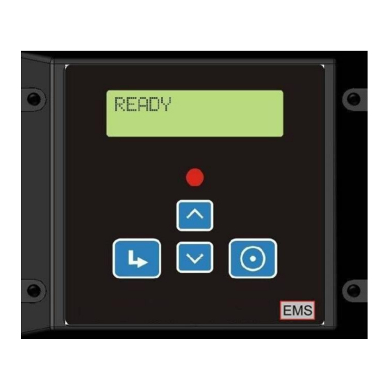
Page 5: Physical Form
EMS 372 GENSET CONTROLLER 3. Physical Form Front View Back View Confidential www.ems.gen.nz Page 5... -
Page 6: Functions
EMS 372 GENSET CONTROLLER 4. Functions 4.1 System Function Description Protection Shutdown Automatic preventative engine and genset shutdown in the event of abnormal operating conditions with optional configuration parameters and clear LCD status messages Manual Start In response to the front panel pushbutton performs a fully... -
Page 7: Generator Ac Monitoring
EMS 372 GENSET CONTROLLER pressure remains within configured limits. Exceeding these limits will result in automatic engine shutdown to prevent damage. Oil Temperature Monitors engine oil temperature with optional configuration parameters and clear LCD status messages this ensures the engine temperature remains within configured limits. -
Page 8: Mains Ac Monitoring
EMS 372 GENSET CONTROLLER configuration parameters and clear LCD status messages. AC Phase Reversal Monitors Genset AC for Phase reversal with optional configuration parameters and clear LCD status messages. AC Loading Monitors AC load as a percentage of full load with optional configuration parameters and clear LCD status messages. -
Page 9: Genset Lcd Displays
EMS 372 GENSET CONTROLLER High oil temperature Engine oil temperature high High engine temperature Engine temperature high Low coolant level Radiator water level low Low fuel level Engine fuel level low High canopy temperature Engine canopy temperature high Engine Hours... -
Page 10: Digital Inputs
EMS 372 GENSET CONTROLLER Lubrication Oil Pressure Engine oil pressure. Engine Temperature Engine coolant temperature (Air or Water). Radiator Water Level Engine radiator water level. Fuel Level Engine fuel level. Oil Temperature Engine oil Temperature Canopy Temperature Engine canopy temperature. -
Page 11: Operation
EMS 372 GENSET CONTROLLER 5. Operation Front Layout 5.1 Buttons Button Function Description Start button / Menu Previous Used to initiate generator start sequence Used as system menu previous or value down button Stop button / Menu Next Used to initiate generator stop sequence... -
Page 12: Password Access
EMS 372 GENSET CONTROLLER 5.3 Password Access The unit requires a password before allowing the user to access Setup Menu items. There are different passwords for Installation, Servicing and Factory level. 5.4 Initial Power Up On power up, the unit displays Logo. -
Page 13: To Stop The Genset
EMS 372 GENSET CONTROLLER o If PREHEAT is selected then the PREHEAT Output will activate for the time specified FUEL-ON. o If ETR (Energise To Run) fuel control is configured, the unit will control the fuel output and display FUEL ON and the proceeds to the CRANK state. -
Page 14: Automatic Operation
EMS 372 GENSET CONTROLLER o If ETS fuel control has been selected then the Fuel output will be energised for the Max Fuel Time or until the engine stops. The stopping process will retry if the engine fails to stop the first time. During the ‘ETS Rest period’ the Fuel output is deactivated. -
Page 15: Display Operation
EMS 372 GENSET CONTROLLER “Cool Down” follows “Run On” and allows the engine and/or generator to cool down before stopping. The cool time is adjustable. At the start of “Cool Down” the Contactor A & B Outputs are deactivated, transferring the load to the mains. The display shows “Cool Down”... - Page 16 EMS 372 GENSET CONTROLLER Mains 50.0Hz 233 232 233 ML1-2 L2-3 L3-1 400 400 GV1 V2 232 233 231 GL1-2 L2-3 L3-1 400 400 GI1 GI2 GI3 10.5 10.6 10.4 Manual Gen Freq 50.0 Hz KW1 KW2 +10.2 +10.1 +10.3...
-
Page 17: Alarms And Warnings
EMS 372 GENSET CONTROLLER Manual Gen KWHr Manual Contact A --/-- XXXX --=-- B Then Returns to the first screen If warnings are present, the associated messages are included in the scroll list, and are interleaved with each status display. A typical Warning will display is as follows:... - Page 18 EMS 372 GENSET CONTROLLER LCD. Once the maintenance timer has expired, pressing the button for 30 seconds will reset it. Minus current indicates that the current measured on Lx (x being 1,2 or Minus Current Lx 3) is reversed. This is probably due to reversed CT wiring or importing power.
- Page 19 EMS 372 GENSET CONTROLLER The engine has failed to stop. Stop Fail Check stop solenoid, check rack operation. The Oil Pressure sensor system is not functioning as expected. Oil-P Fault Check oil pressure sensor and associated wiring. The Engine Temperature Sensor is not functioning as expected.
-
Page 20: Inputs Electrical Specification
EMS 372 GENSET CONTROLLER High V3 Volts Voltage on genset Phase V3 is High High Frequency Genset frequency is high Low Frequency Genset frequency is low Alarms are indicated by fast flashing of the alarm LED and displaying the appropriate message on the LCD. - Page 21 EMS 372 GENSET CONTROLLER Sensor Current limited exciting voltage 10V at 10mA approx Engine Suitable for either resistive or switch C.O.F. senders Temperature Analog/Digital Current limited exciting voltage 10V at 10mA approx Sensor Suitable for analog use with EMS08 temperature sensor or Canopy switch C.O.F input...
-
Page 22: Outputs Electrical Specification
EMS 372 GENSET CONTROLLER Main Phase 2 Volts Voltage Max 230VRMS Main Phase 3 Volts Voltage Max 230VRMS Main Phase Neutral Volts Voltage Max 230VRMS Phase 1 Amps CT Loop Amps 5A RMS Continuous. 6.25A Peak Phase 2 Amps CT Loop Amps 5A RMS Continuous. -
Page 23: Battery Charging Alternator Excitation
EMS 372 GENSET CONTROLLER to and from the load. Contactor outputs are controlled in both Manual and Auto operating modes. The Mains contactor output is controlled to deactivate the Mains contactor when the start button is pressed or the autostart input is activated. The time of opening can be selected to respond immediately on an autostart input or a start button press. -
Page 24: Set-Up
10. Set-up In the factory environment the unit can be setup by the EMS Cloning Utility or by the EMS Windows setup utility. In the field, adjustments to the unit can be made using the buttons on the front panel. -
Page 25: System Column
EMS 372 GENSET CONTROLLER Once the bottom of the column has been reached, the unit displays “Top Press Stop”. Pressing the STOP button takes the user to the top of the column. Setup mode automatically terminates if no button in pressed for 60 seconds, or when the exit item is accessed. - Page 26 EMS 372 GENSET CONTROLLER Item Range Default Description Note: This item is only displayed when Fuel Select = ETS (See Above) ETS Tries 1 - 2 Maximum Stop Retries for ETS Fuel Control Note: This item is only displayed when Fuel Select = ETS 5 –...
- Page 27 EMS 372 GENSET CONTROLLER Item Range Default Description Selects Canopy temperature sensor type. COF = Switch: Close on Fault CTemp Type EMS08 EMS08 = EMS08 temperature sensor with an FSD of EMS08 100ºC CTemp High canopy temperature alarm shutdown set point.
- Page 28 EMS 372 GENSET CONTROLLER Item Range Default Description the Oil temperature goes above 50 ºC Oil protection sensor mode. Switch Switch = Protection from switch input only Sender Oil Prot Switch Sender = Protection from analog input only Both Both = Combined protection Oil Check Checks for oil pressure prior to cranking.
-
Page 29: Timers Column
EMS 372 GENSET CONTROLLER Item Range Default Description On = Engine protection functions are enabled. (Normal setting) Off = All protection shutdown mechanisms for the engine are disabled. Warnings and Alarms continue to be indicated. Stop on Alm Off should only be chosen for mission critical applications when shutdown is not permitted and the engine can run to destruction. -
Page 30: Contactor A Column
EMS 372 GENSET CONTROLLER Item Range Default Description Duration that the Test Mode will run before the Genset 0 – 740 is shut down. Test Time minutes 0 = Run until user presses the manual Stop button. Maintenanc 50 – 1000 Hours between Maintenance Requests 10.5... -
Page 31: Ac Setup Column
EMS 372 GENSET CONTROLLER Item Range Default Description Min = Minutes Selects the time for which the Autostart has to be 1 – 600 StartRestor restored before the start delay timer is reset and starting aborted. Prestart warning time. If an output has been 0 –... -
Page 32: Agf Setup Column
EMS 372 GENSET CONTROLLER 50 – 70 The maximum frequency above which the Genset is Hi Hz Trip started. 10.9 AGF Setup Column Item Range Default Description 60 – 240 The minimum voltage below which the Genset is Lo Volt Trip... -
Page 33: I/O Setup Column
EMS 372 GENSET CONTROLLER Item Range Default Description The maximum line to line genset voltage above Hi L-LV Trip 195-530 which Generator shutdown 10.10 I/O Setup Column Item Range Default Description Selectable Digital Output Function from one of the following:... -
Page 34: Communications
EMS 372 GENSET CONTROLLER Item Range Default Description 1200 2400 4800 Baud Rate 9600 9600 Comms Port Baud Rate 19200 38400 57600 Data Bits 7 – 9 Number of Data Bits Even Parity None Parity Select None Stop Bits 1 or 2... - Page 35 EMS 372 GENSET CONTROLLER Relative Humidity 95% non-condensing Standby < 7mA Supply Current Running 50mA AC Voltage Range L-N = 350VRMS. AC Frequency Range 40 – 70Hz CT current range 0 – 5A + 25% Overload Overall Accuracy Class 1 Digital Output Rating Open Drain Relay Coil Driver.
-
Page 36: Installation And Wiring
EMS 372 GENSET CONTROLLER 12. Installation and Wiring NB: The unit is a complex electronic device and caution should be taken to ensure correct wiring before power is applied. The unit is fitted with 2, 6 ,4 and 10 way Molex Minifit or equivalent socket connectors for which mating plugs can be selected from the Amp PE, or TPK range. -
Page 37: Connector Detail
EMS 372 GENSET CONTROLLER 12.1 Connector Detail Connector Assignment Connection Information J7: Data Port Programming and Auxiliary Unit data port. NB: Connect ONLY manufacturer approved equipment to this port Connection Common –ve. This connection must be made directly to the engine block for lowest electrical noise. -
Page 38: Trouble Shooting
EMS 372 GENSET CONTROLLER Connector Assignment Connection Information Contactor A Output Contactor B Output Excitation Output Connection Gen AC Phase 1 J4 = AC Inputs for Genset Gen AC Phase 2 Gen AC Phase 3 Gen AC Neutral Connection Main AC Phase 1... - Page 39 EMS 372 GENSET CONTROLLER Message Cause Engine temperature has exceeded the high temperature set point. High Engine Temp The temperature icon turns on. This message may also be shown as “High Water Temperature” depending on temperature system setup. Oil temperature has exceeded the high temperature set point. The High Oil Temperature oil pressure icon turns on.
- Page 40 EMS 372 GENSET CONTROLLER Message Cause The unit has detected that the oil pressure is above the oil pressure alarm setpoint with the engine not running. This warning prevents the engine from attempting to crank with the engine potentially Oil Lock Out running.
-
Page 41: Wiring Options
EMS 372 GENSET CONTROLLER 14. Wiring Options Crankcase Crankcase Crankcase Crankcase Crankcase Crankcase Crankcase Temperature Sensing Options Oil Pressure Sensing Options Side Mounting Top Mounting Water Level Probe Water Level Radiator Probe T op Radiator Side Crankcase Crankcase Note: The radiator must be electrically bonded to the crankcase common. -
Page 42: Engine Sensor Tables
EMS 372 GENSET CONTROLLER Typical Contactor Control 15. Engine Sensor Tables 10-180 Oil Pressure Sensor Ohms Pressure in BAR TS150 Engine Temperature Sensor Ohms Temperature 322.8 179.5 112.5 62.2 48.1 36.5 28.9 23.1 18.6 Confidential www.ems.gen.nz Page 42... - Page 43 EMS 372 GENSET CONTROLLER EMS08 Room Temperature Sensor Ohms Temperature 276.3 248.1 214.1 142.2 47.1 30.8 Confidential www.ems.gen.nz Page 43...
Need help?
Do you have a question about the EMS372 and is the answer not in the manual?
Questions and answers