
Subscribe to Our Youtube Channel
Related Manuals for Endress+Hauser micropilot S FMR 533


Summary of Contents for Endress+Hauser micropilot S FMR 533
- Page 1 micropilot S BA 209F/00/en/04.04 Nr. 52006313 FMR 533 Valid as of software version: V 01.02.00 (amplifier) V 01.02.00 (communication) Level-Radar Operating Instructions...
- Page 2 Brief operating instructions Micropilot S FMR 533 Brief operating instructions KA 161F/00/a2/12.01 Micropilot S - Quick Setup 52006294 Contrast: measured value history dist./ reset meas value Group selection basic setup tank medium process empty full pipe dist./ check range of...
-
Page 3: Table Of Contents
Quick wiring guide ..... 29 Contact addresses of Endress+Hauser ..85 Connecting the measuring unit ... 31 Equipotential bonding . -
Page 4: Safety Instructions
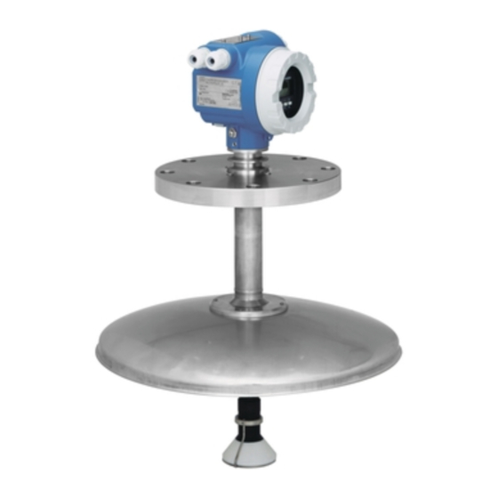
Safety instructions Designated use The Micropilot S FMR 533 is a compact radar level transmitter for the continuous, contactless measurement of liquids, pastes and sludge in stilling wells. The device can also be freely mounted outside closed metal vessels because of its operating frequency of about 6 GHz and a maximum radiated pulsed energy of 1mW (average µ... -
Page 5: Return
Micropilot S FMR 533 1 Safety instructions Return The following procedures must be carried out before a transmitter is sent to Endress+Hauser for repair: • Always enclose a duly completed "Declaration of contamination" form. Only then can Endress +Hauser transport, examine and repair a returned device. -
Page 6: Safety Instructions
1 Safety instructions Micropilot S FMR 533 Notes on safety conventions and symbols In order to highlight safety-relevant or alternative operating procedures in the manual, the following conventions have been used, each indicated by a corresponding symbol in the margin. -
Page 7: Identification
Registration No Dat./Insp.: X X X X X X ATEX Safety information Fig. 1 Information on the nameplate of the Micropilot S FMR 533 (example) Year of construction Tank reference height Tank-no. Certification no Hersteller / Producer : ENDRESS+HAUSER MICROPILOT S FMR Zertifikat-Nr. - Page 8 2 Identification Micropilot S FMR 533 2.1.2 Ordering structure Ordering structure Micropilot S FMR 533 Certificates Basic weight A For non-hazardous areas 13.0 kg G ATEX II 3G EEx nA II T6 K TIIS Ex ia IIC T3 TIIS Ex ia IIC T6...
-
Page 9: Scope Of Delivery
"Protection Measures for Electrical Equipment for Measurement, Control, Regulation and Laboratory Procedures". The instrument described in this manual thus complies with the statutory requirements of the EG directives. Endress+Hauser confirms the successful testing of the instrument by affixing to it the CE mark. -
Page 10: Mounting
3 Mounting Micropilot S FMR 533 Mounting Quick installation guide Observe orientation when installing! Installation in tank (free space): Mark on process connector facing the nearest tank wall! Turn housing The housing can be turned in marker at flange neck... -
Page 11: Incoming Acceptance, Transport, Storage
Micropilot S FMR 533 3 Mounting Incoming acceptance, transport, storage 3.2.1 Incoming acceptance Check the packing and contents for any signs of damage. Check the shipment, make sure nothing is missing and that the scope of supply matches your order. -
Page 12: Installation Conditions
ENDRESS+HAUSER Micropilot II marker E+H UNI flange (max. 1 bar) flange hub Ø 99.5 (3.92") DIN, ANSI, JIS Ø 118 (4.65") Ø 454 (17.87") deflector rod Ø 3 mm Ø 81 (3.19") Fig. 4 Dimensions Micropilot S FMR 533 Endress+Hauser... - Page 13 Micropilot S FMR 533 3 Mounting 3.3.2 Engineering hints Orientation • Recommended distance (1) wall – outer edge of nozzle: ~ 1/6 of tank diameter. • Mount the Micropilot S at a position where the tank movement due to filling/ emptying of the tank is of low influence.
- Page 14 3 Mounting Micropilot S FMR 533 Beam angle The beam angle is defined as the angle α where the energy density of the radar waves reaches half the value of the maximum energy density (3dB-width). Microwaves are also emitted outside the signal beam and can be reflected off interfering installations.
- Page 15 • This safety distance (SD) is set to 0.5 m (20") by default and generating an alarm in case the level rises inside the safety distance. • For Micropilot S FMR 533 with parabolic antenna, this safety distance should be set to 0.5 m (20"). The response of the signal output should be configured to "alarm "...
- Page 16 1) Treat Ammonia NH3 as a medium of group A, e.g. always use a stilling well. Measuring range depending on product class for Micropilot S FMR 533: Product class Free space (Storage tank)
- Page 17 Micropilot S FMR 533 3 Mounting Blocking distance The blocking distance (= BD) is the minimum distance form the reference point of the measurement (mounting flange) to the medium surface at maximum level. Blocking distance Free space (Storage tank) (BD)
-
Page 18: Installation Instructions
3 Mounting Micropilot S FMR 533 Installation instructions 3.4.1 Mounting kit In addition to the tool needed for flange mounting, you will require the following tool: • 4 mm Allen wrench for turning the housing. 3.4.2 Installation in tank (free space) - Page 19 Micropilot S FMR 533 3 Mounting Examples for installation in a manway inclination rings with O-ring (Viton) see construction hits on page 30 for installation in nozzle you can dismantle standard installation the parabolic reflector nozzle 4 bolts hinged flange...
- Page 20 3 Mounting Micropilot S FMR 533 3.4.3 Turn housing After mounting, the housing can be turned 350° in order to simplify access to the display and the terminal compartment. Proceed as follows to turn the housing to the required position: •...
- Page 21 Micropilot S FMR 533 3 Mounting 3.4.4 Mounting with E+H UNI flange Installation hints E+H UNI flanges are designed for non-pressurized operation respectively max. 1 bar absolute pressure. The number of bolts has sometimes been reduced. The bolt-holes have been enlarged for adaption of dimensions, therefore, the flange needs to be properly aligned to the counterflange before the bolts are tightened.
- Page 22 3 Mounting Micropilot S FMR 533 Preparation for the installation of the E+H UNI flange Endress+Hauser...
- Page 23 Micropilot S FMR 533 3 Mounting Endress+Hauser...
- Page 24 A special reflector can be used for applications on floating roofs (not for FMR 532 with planar antenna!). Construction hints Note! The roof reflector is not part of the standard offering from Endress+Hauser. Endress+Hauser...
- Page 25 Micropilot S FMR 533 3 Mounting Optimum mounting position Positioning of the reflector on a floating roof: • The upper edges of the reflector have to be aligned horizontally. • For slanted locations (e.g. dome- shaped floating roof), the feet must be extended accordingly.
- Page 26 3 Mounting Micropilot S FMR 533 3.4.6 Mounting with Inclination device Installation hints The inclination can be adjusted up to 6° by means of an inclination device. The purpose is to align the antenna axis such that the radar beam is directed straight to the product surface.
- Page 27 The purpose is to align the antenna axis such that the radar beam is directed straight to the product surface. Note! The alignment unit is not part of the standard offering from Endress+Hauser, special offers available under ref. number MVT6M0081. Endress+Hauser...
-
Page 28: Post-Installation Check
3 Mounting Micropilot S FMR 533 Post-installation check After the measuring instrument has been installed, perform the following checks: • Is the measuring instrument damaged (visual check)? • Does the measuring instrument correspond to the measuring point specifications such as process temperature/pressure, ambient temperature, measuring range, etc.? •... -
Page 29: Wiring
Micropilot S FMR 533 4 Wiring Wiring Quick wiring guide When grounding conductive screens, the corresponding directives EN 60079-14 and EN 1127-1 must be observed. Recommendation for safe grounding of conductive screens: Wiring " Before connection please note the following:... - Page 30 4 Wiring Micropilot S FMR 533 Wiring with Tank Side Monitor NRF 590 " Before connection please note the following: ENDRESS+HAUSER MICROPILOT S 0560 The power supply must be identical to the data on the Order Code: Caution! if modification nameplate (1).
-
Page 31: Connecting The Measuring Unit
Micropilot S FMR 533 4 Wiring Connecting the measuring unit Terminal compartment The housing comes with a separate terminal compartment. Load HART Ω Minimum load for Hart communication: 250 Cable entry Cable gland: M20x1.5 or Pg13.5 Cable entry: G ½ or ½ NPT Supply voltage Direct current voltage: 16…36 VDC... - Page 32 4 Wiring Micropilot S FMR 533 4.2.1 Connection to Tank Side Monitor NRF590 See Page 30. 4.2.2 HART connection with two E+H RN 221 N - ToF Tool FXA 193 power supply 4...20 mA signal df das. df das. dsdmdm...
-
Page 33: Equipotential Bonding
Micropilot S FMR 533 4 Wiring Equipotential bonding Connect the Equipotential bonding to the external ground terminal of the transmitter. " Caution! In Ex applications, the instrument must only be grounded on the sensor side. Further safety instructions are given in the separate documentation for applications in explosion hazardous areas. -
Page 34: Operation
5 Operation Micropilot S FMR 533 Operation Quick operation guide ENDRESS + HAUSER – >3 s Return to basic setup tank shape medium property Group Selection dome ceiling unknown safety settings horizontal cyl DC: < 1.9 bypass DC: 1.9 ... 4... - Page 35 Micropilot S FMR 533 5 Operation 5.1.1 General structure of the operating menu The operating menu is made up of two levels: • Function groups (00, 01, 03, …, 0C, 0D): The individual operating options of the instrument are split up roughly into different function groups.
-
Page 36: Display And Operating Elements
5 Operation Micropilot S FMR 533 Display and operating elements Fig. 5 Layout of the display and operating elements 5.2.1 Display Liquid crystal display (LCD): Four lines with 20 characters each. Display contrast adjustable through key combination. Headline Position indicator... - Page 37 Micropilot S FMR 533 5 Operation 5.2.2 Display symbols The following table describes the symbols that appear on the liquid crystal display: Symbols Meaning ALARM_SYMBOL This alarm symbol appears when the instrument is in an alarm state. If the symbol flashes, this indicates a warning.
- Page 38 5 Operation Micropilot S FMR 533 5.2.3 Key assignment The operating elements are located inside the housing and are accessible for operation by opening the lid of the housing. Function of the keys Key(s) Meaning Navigate upwards in the selection list...
-
Page 39: Local Operation
Micropilot S FMR 533 5 Operation Local operation 5.3.1 Locking of the configuration mode The Micropilot can be protected in two ways against unauthorised changing of instrument data, numerical values or factory settings: "unlock parameter" (0A4): A value <> 100 (e.g. 99) must be entered in "unlock parameter" (0A4) in the "diagnostics"... - Page 40 There is no need to change these parameters under normal circumstances and consequently, they are protected by a special code known only to the E+H service organization. Please contact Endress+Hauser if you have any questions. Endress+Hauser...
- Page 41 Micropilot S FMR 533 5 Operation 5.3.3 Factory settings (Reset) " Caution! A reset sets the instrument back to the factory settings. This can lead to an impairment of the measurement. Generally, you should perform a basic setup again following a reset.
-
Page 42: Display And Acknowledging Error Messages
5 Operation Micropilot S FMR 533 Display and acknowledging error messages Type of error Errors that occur during commissioning or measuring are displayed immediately on the local display. If two or more system or process errors occur, the error with the highest priority is the one shown on the display. -
Page 43: Hart Communication
5.5.2 ToF Tool operating program The ToF Tool is a graphical operating software for instruments from Endress+Hauser that operate based on the time-of-flight principle. It is used to support commissioning, securing of data, signal analysis and documentation of the instruments. It is compatible with the following operating systems: Win95, Win98, WinNT4.0, Win2000 and... - Page 44 5 Operation Micropilot S FMR 533 Menu-guided commissioning Signal analysis via envelope curve Connection options: • Service-interface with adapter FXA 193 (see Page 32) • HART with Commubox FXA 191 (see Page 32) Endress+Hauser...
- Page 45 Micropilot S FMR 533 5 Operation 5.5.3 Commuwin II-Operating Programm Commuwin II is an operating software with graphical support for intelligent transmitters with the communication protocols Rackbus, Rackbus RS 485, INTENSOR, HART or PROFIBUS-PA. It is compatible with the operating systems Win 3.1/3.11, Win95, Win98 and WinNT4.0.
-
Page 46: Commissioning
6 Commissioning Micropilot S FMR 533 Commissioning Function check Make sure that all final checks have been completed before you start up your measuring point: • Checklist “Post installation check” (see Page 28 ff.). • Checklist “Post connection check” (see Page 33 ff.). -
Page 47: Basic Setup
Micropilot S FMR 533 6 Commissioning Basic Setup Commissioning flange: reference point of measurement measuring cond. measuring cond. empty calibr. full calibr. pipe diameter (for bypass/stilling well) E = empty calibr. (= zero) = full calibr. (= span) settings in 005... - Page 48 6 Commissioning Micropilot S FMR 533 To successfully commission a precise measurement to the nearest mm, it is important you carry out a history reset on first installation after mechanical installation and after the basic setup of the device (see Page 56). Only after a history reset the mounting calibration is carried out.
-
Page 49: Basic Setup With The Vu 331
Micropilot S FMR 533 6 Commissioning Basic Setup with the VU 331 Function "measured value" (000) ⇒ This function displays the current measured value in the selected unit (see "customer unit" (042) function). The number of digits after decimal point can be selected in the "no.of decimals"... - Page 50 6 Commissioning Micropilot S FMR 533 Function "medium property" (003) ⇒ This function is used to select the dielectric constant. Selection: • unknown • < 1.9 • 1.9 ... 4 • 4 ... 10 • > 10 ε Product class...
- Page 51 Micropilot S FMR 533 6 Commissioning Function "process cond." (004) ⇒ This function is used to select the process conditions. Selection: • standard • calm surface • turb. surface • agitator • fast change • test:no filter standard calm surface...
- Page 52 6 Commissioning Micropilot S FMR 533 Function "empty calibr." (005) ⇒ This function is used to enter the distance from the flange (reference point of the measurement) to the minimum level (=zero). " Caution! For dish bottoms or conical outlets, the zero point should be no lower than the point at which the radar beam hits the bottom of the tank.
- Page 53 Micropilot S FMR 533 6 Commissioning Note! If bypass or stilling well was selected in the "tank shape" (002) function, the pipe diameter is requested in the following step. Function "pipe diameter" (007) ⇒ This function is used to enter the pipe diameter of the stilling well or bypass pipe.
- Page 54 6 Commissioning Micropilot S FMR 533 Function "check distance" (051) ⇒ This function triggers the mapping of interference echoes. To do so, the measured distance must be compared with the actual distance to the product surface. The following options are available for selection: Selection: •...
- Page 55 Micropilot S FMR 533 6 Commissioning Function "range of mapping" (052) ⇒ This function displays the suggested range of mapping. The reference point is always the reference point of the measurement (see Page 47 ff.). This value can be edited by the operator.
- Page 56 6 Commissioning Micropilot S FMR 533 Display "dist./meas.value (008)" ⇒ The distance measured from the reference point to the product surface and the level calculated with the aid of the empty alignment are displayed again. Check whether the values correspond to the actual level or the actual distance. The following cases can occur: •...
-
Page 57: Mounting Calibration With Vu 331
Micropilot S FMR 533 6 Commissioning Mounting calibration with VU 331 6.5.1 Function group "mounting calibr." (03) ⇒ Function "tank gauging" (030) ⇒ Using this function, you can either enter a dip table or carry out an auto-correction. Function "auto correction" (031) ⇒... - Page 58 6 Commissioning Micropilot S FMR 533 " Caution! During the learning period, fast filling/emptying or turbulent surfaces can result in switching off and on the phase evaluation. Subsequently observed measurement errors will disappear as soon as tank levels come back to areas measured by Micropilot S previously with activated phase evaluation.
- Page 59 Micropilot S FMR 533 6 Commissioning Display "custody mode" (0A9) ⇒ This indicates the instrument calibration mode. The calibration mode (active) can be set using the hardware security lock on the electronics (see Page 36). Selection: • inactive • active pos.
- Page 60 6 Commissioning Micropilot S FMR 533 Dip table The dip table is used to correct the level readings of the Micropilot S using independently taken hand dips. The dip table is used in particular to adapt the level gauge to the specific application conditions as mechanical offset and tank/stilling well design.
- Page 61 Micropilot S FMR 533 6 Commissioning Note! The offset should NOT be determined and entered within the close range of the antenna (conf. definition of the safety distance) or immediately in the range of the tank bottom, because within these ranges interferences of the radar signal may occur.
- Page 62 6 Commissioning Micropilot S FMR 533 manual The value pairs in the dip table can be read and written. You can enter the measured value and the dip value. – uncorrected measured value: This is the measured value supplied by the instrument, NOT corrected by the dip table.
- Page 63 Micropilot S FMR 533 6 Commissioning Function "dip table handl." (036) ⇒ Use this function to enter the dip value (level or distance) which will correct the measurement values. Selection: • new point • edit point • store point • delete point •...
- Page 64 6 Commissioning Micropilot S FMR 533 return By selecting this point, you return to the function "dip table mode" (033). next point This scrolls down in the table. If the table is empty, you can still select this option. However, the displayed value does not change.
- Page 65 Micropilot S FMR 533 6 Commissioning 6.5.2 Envelope curve with VU 331 After the basic setup, an evaluation of the measurement with the aid of the envelope curve ("display" (09) function group) is recommended. Function "plot settings" (09A) ⇒ Here you can select which information is shown on the display: •...
-
Page 66: Basic Setup With The Tof Tool
6 Commissioning Micropilot S FMR 533 Basic Setup with the ToF Tool To carry out the basic setup with the ToF Tool operating program, proceed as follows: • Start the ToF Tool operating program and establish a connection • Select the "basic setup" function group in the navigation bar... - Page 67 Micropilot S FMR 533 6 Commissioning Basic Setup step 2/5: • Enter the application parameters: – tank shape (for a description, see Page 49) – medium property (for a description, see Page 50) – process cond. (for a description, see Page 51) Basic Setup step 3/5: If "dome ceiling"...
- Page 68 6 Commissioning Micropilot S FMR 533 If "horizontal cyl" or "sphere" is selected in the "tank shape" function, the following display appears on the screen: • empty calibr. (for a description, see Page 52) • full calibr. (for a description, see Page 52) If "stilling well"...
- Page 69 Micropilot S FMR 533 6 Commissioning If "flat ceiling" is selected in the "tank shape" function, the following display appears on the screen: • empty calibr. (for a description, see Page 52) • full calibr. (for a description, see Page 52) Basic Setup step 4/5: •...
- Page 70 6 Commissioning Micropilot S FMR 533 6.6.1 Envelope curve with the ToF Tool After the basic setup, an evaluation of the measurement using the envelope curve is recommended. Note! If the level of echo is very weak or there is a heavy interference echo, an orientation of the Micropilot can help optimise the measurement (increase of the useful echo/ reduction of the interference echo) (see »Quick installation guide«).
-
Page 71: Mounting Calibration With The Tof Tool
Micropilot S FMR 533 6 Commissioning Mounting calibration with the ToF Tool To carry out the basic setup with the ToF Tool operating program, proceed as follows: • Start the ToF Tool operating program and establish a connection • Select the "mounting calibr." function group in the navigation bar... - Page 72 6 Commissioning Micropilot S FMR 533 Mounting calibration step 2/2: • dip table mode (description see Page 61) • meas. v. (description see Page 62) • dip value (see Page 62) • dip table handl. (description see Page 63) • dip table state (description see Page 61) •...
-
Page 73: Maintenance
Micropilot S FMR 533 7 Maintenance Maintenance The Micropilot S measuring instrument requires no special maintenance. Exterior cleaning When cleaning the exterior of measuring devices, always use cleaning agents that do not attack the surface of the housing and the seals. -
Page 74: Accessories
8 Accessories Micropilot S FMR 533 Accessories Various accessories, which can be ordered separately from Endress+Hauser, are available for the Micropilot S. Weather protection cover A Weather protection cover made of stainless steel is available for outdoor mounting (order code: 543199-0001). The shipment includes the protective cover and tension clamp. -
Page 75: Trouble-Shooting
Micropilot S FMR 533 9 Trouble-shooting Trouble-shooting Trouble-shooting instructions Endress+Hauser... -
Page 76: System Error Messages
9 Trouble-shooting Micropilot S FMR 533 System error messages Code Description Possible cause Remedy A102 checksum error device has been powered off reset; general reset & new before data could be stored; emc avoid emc problem; if alarm calibr.required problem; E²PROM defect... - Page 77 Micropilot S FMR 533 9 Trouble-shooting Code Description Possible cause Remedy A270 custody switch undef switch for custody transfer may be check position of custody check position defective switch exchange electronics inconsistency between phase and check basic calibration amplitude evaluation...
-
Page 78: Application Errors
9 Trouble-shooting Micropilot S FMR 533 Application errors Error Output Possible cause Remedy A warning or Depending on the configuration See table of 1. See table of error messages alarm has error messages (see page 76) occurred. (see page 76) →... - Page 79 Micropilot S FMR 533 9 Trouble-shooting Error Output Possible cause Remedy If the surface is Signal is weakened 1. Carry out tank mapping → not calm by the rough surface basic setup (e.g. filling, — the interference 2. Set the process cond. (004) to...
-
Page 80: Orientation Of The Micropilot
9 Trouble-shooting Micropilot S FMR 533 Orientation of the Micropilot For orientation a marker is found on the flange or threaded boss of the Micropilot. During installation this must be oriented as follows: • In tanks: to the vessel wall •... - Page 81 Micropilot S FMR 533 9 Trouble-shooting c) Vessel empty, no interference echo: d) Vessel empty, interference echo obtained: 7. Fix the flange or threaded boss in this position. If necessary, replace the seal. 8. Carry out tank mapping, siehe Kapitel 6.1 bzw. 6.2.
-
Page 82: Spare Parts
9 Trouble-shooting Micropilot S FMR 533 Spare parts Note! You can order spare parts directly from your E+H service organization by giving the order code and the serial number which is printed on the measuring transducer nameplate (see Page 7 ff.). The corresponding spare part number also appears on each spare part. - Page 83 Micropilot S FMR 533 9 Trouble-shooting Endress+Hauser...
-
Page 84: Return
Return If you need to send a Micropilot back to Endress+Hauser for repair, please send a completed copy of the form printed on the last page. • An exact description of the application. -
Page 85: Software History
– HART communicator DXR 375 with Rev. 1, DD 1. Contact addresses of Endress+Hauser The addresses of Endress+Hauser are given on the back cover of this operating manual. If you have any questions, please do not hesitate to contact your E+H representative. -
Page 86: Technical Data
The Micropilot S can be used for measurement in a stilling well as well as in free space. The different instrument versions are applied as follows: • The Micropilot S FMR 533 with parabolic antenna is preferred for free- space measurements. The Micropilot S FMR 530 with horn antenna can be used as an alternative for small nozzle diameters . - Page 87 Micropilot S FMR 533 10 Technical data Auxiliary energy Electrical connection Housing T 12 with separate terminal compartment. Minimum load for HART communication: 250 Ω Load HART Cable entry Cable gland: M20x1.5 or Pg13.5 Cable entry: G ½ or ½ NPT Supply voltage see Page 31 ff.
- Page 88 10 Technical data Micropilot S FMR 533 Inventory Control All device types can be delivered as "Inventory Conctrol Versions" with a Versions reduced accuracy of ± 3mm (under reference conditions). To these versions, the calibration certificate or custody transfer type approval is NOT attached.
- Page 89 Page 34 Certificates and approvals CE approval The measuring system meets the legal requirements of the EC-guidelines. Endress+Hauser confirms the instrument passing the required tests by attaching the CE-mark. RF approvals R&TTE 1999/5/EG, FCC CRF 47, part 15 Overspill protection...
-
Page 90: Appendix
11 Appendix Micropilot S FMR 533 Appendix 11.1 Operating menu HART (Display modul), ToF Tool basic setup tank shape medium property process cond. empty calibr. full calibr. dome ceiling unknown standard enter value enter value horizontal cyl. DK: < 1.9 calm surface DK: 1.9 …... - Page 91 Micropilot S FMR 533 11 Appendix dist./meas.value check distance range of mapping start mapping history reset distance = ok input of dist. too small mapping range D and L dist. too big are displayed manual dist. unknown safety distance in safety dist.
-
Page 92: Operating Matrix Hart / Commuwin Ii
11 Appendix Micropilot S FMR 533 11.2 Operating matrix HART / Commuwin II Endress+Hauser... -
Page 93: 11.3 Description Of Functions
Micropilot S FMR 533 11 Appendix 11.3 Description of functions Note! A detailed description of the function groups, functions and parameters is given in the documentation BA 217F/00/en - a description of the instrument functions of the Micropilot S. Endress+Hauser... -
Page 94: 11.4 Function And System Design
11 Appendix Micropilot S FMR 533 11.4 Function and system design 11.4.1 Measuring principle The Micropilot is a "downward-looking" measuring system, operating based on the time- of-flight method. It measures the distance from the reference point (process connection) to the product surface. Radar impulses are emitted by an antenna, reflected off the product surface and received again by the radar system. - Page 95 <150 mm. However, for these diameters no custody transfer approval is available. • The Micropilot S FMR 533 with parabolic antenna is preferred for free-space measurements. The Micropilot S FMR 530 with horn antenna can be used as an alternative for small nozzle diameters .
- Page 96 • with display and operating module VU 331, • with a Personal Computer, FXA 193 and the operating software ToF Tool. The ToF Tool is a graphical operating software for instruments from Endress+Hauser that operate based on the time-of-flight principle (radar, ultrasonic, guided micro- impulse).
- Page 97 Micropilot S FMR 533 11 Appendix 11.4.3 Custody transfer mode Micropilot S is a weight and measure approved level transmitter. Either the innage or the ullage can be selected as the custody transfer variable. The selected variable is the basis for the subsequent calculation of the current amount of product in a tank, along with other measured variables such as (average) temperature and pressure.
- Page 98 11 Appendix Micropilot S FMR 533 11.4.5 Particularities in "approved" operation The Micropilot S level radar is set to custody transfer mode after commissioning using a custody locking switch (see Page 38). The position of the custody locking switch is secured and sealed using the sealing pin.
- Page 99 11 Appendix 11.4.7 Integrated on tank gauging system The Endress+Hauser Tank Side Monitor NRF 590 provides integrated communications for sites with multiple tanks, each with one or more sensors on the tank, such as radar, spot or average temperature, capacitive probe for water detection and/or pressure sensors.
- Page 100 11 Appendix Micropilot S FMR 533 This product may be protected by at least one of the following patents. Further patents are pending. • US 5,387,918 EP 0 535 196 • US 5,689,265 EP 0 626 063 • US 5,659,321 •...
-
Page 101: Index
Micropilot S FMR 533 Index Index Functions ........35 Accessories . - Page 102 Index Micropilot S FMR 533 Selection menu......34 Service adapter FXA 193 ..... 74 Parameter .
- Page 103 Micropilot S FMR 533 Index Declaration of contamination Dear costumer, Because of legal determinations and for the safety of our employes and operating equipment we need this “Declaration of contamination” with your signature before your order can be handled. Please put the completely filled in declaration to the instrument and to the shipping documents in any case.
- Page 104 Poland – Wroclaw Costa Rica – San Jose ❑ Sakura Endress Co. Ltd. ❑ Endress+Hauser Polska Sp. z o.o. Tel. (01) 88 05 60, Fax (01) 88 05 63 35 Euro-Tec S.A. Tel. (0422) 54 06 11, Fax (0422) 55 02 75 Tel.
Need help?
Do you have a question about the micropilot S FMR 533 and is the answer not in the manual?
Questions and answers